[ad_1]
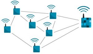
Industrial uses are expected, in wireless sensor nodes and mesh networks.
Maximum input bias current is 15pA at 25°C (100pA -40°C to 125°C) allowing high value feedback resistors to keep power down, and allowing connection to high-impedance sensors.
Both inputs and output are rail-to-rail for wide dynamic range and to simplify single rail operation.
 “An integrated EMI filter provides 114dB electromagnetic interference rejection at 1.8GHz,” said Analog. “With low 1/f noise inherent to its zero-drift architecture the LTC2063 is well suited for amplifying and conditioning low frequency sensor signals in high temperature industrial and automotive systems as well as portable and wireless sensor network applications.”
It is available in SOT-23 or SC70, with the SC70 version including a shut-down pin, which cuts consumption to 90nA.
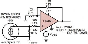
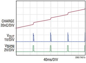
 “This enables ultra-low power duty cycled sensor applications, for example, a precision low duty cycle oxygen sensor circuit (pictured, with charge graph below) in the data sheet consumes less than 200nA average.” Adding that this is <400nW.
 The firm has put some time in to minimise power-up ‘surges’, with a cold switch-on consuming <1.2µA for 1.7ms and enable when the shut-down pin is released using 1.4µA for 500µs. “While some amplifiers exhibit a large start-up current that far exceeds average power consumption, the LTC2063 maintains low current draw even during start-up.”
“LTC2063 is well suited for amplifying and conditioning low frequency sensor signals in high temperature industrial and automotive systems as well as medical, portable, energy harvesting and wireless sensor network applications,” said Analog.
The chip is used alongside an LTP5901-IPM SmartMesh IP module, in the DC2369A wireless current sense reference board which is includes an isolated floating current sense and operates for years on small batteries when reporting at 1Hz.
In the link just above, the LTC2063 is referred to as a ‘chopper amplifier’ while the also ‘zero-drift’ branded LTC2050 is an auto-zero amplifier. Exactly how the 2063 works is not yet revealed. The data sheet says: “Zero-drift amplifiers like the LTC2063 achieve low input offset voltage and 1/f noise by heterodyning DC and flicker noise to higher frequencies”, while goign on to say: “In early zero-drift amplifiers, this process resulted in idle tones at the self-calibration frequency, often referred to as the chopping frequency. These artifacts made early zero-drift amplifiers difficult to use. The advanced circuit techniques used by the LTC2063 suppress these spurious artifacts, allowing for trouble-free use.”
LTC2063 at a glance
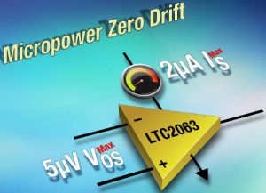
- supply current: 2μA max
- offset voltage: 5μV max
- offset voltage drift: 0.02μV/°C max
- input bias current: 3pA typical, 30pA max -40 to 85°C, 100pA max -40 to 125°c
- integrated EMI filter (114dB rejection at 1.8GHz)
- shut-down current: 90nA typ, 170nA max
- rail-to-rail input and output
- 1.7 to 5.25V supply
- Avol: 140dB typical
- low charge power-up for duty cycled applications
- temperature range: -40 to 85°C or -40 to 125°C
- 6pin SC70 or 5pin TSOT-23
[ad_2]
Source link

