[ad_1]
5G mobile broadband wireless access networks are expected to meet the system and service requirements of new use cases and applications into 2020 and beyond. Connecting industries and enabling new services is the most significant aspect of 5G preparation.
The fourth generation, or 4G LTE, is all about people and places, with communication and information sharing being the core theme. 5G extends the scope to include machines by adding reliable and resilient control and monitoring. This shift has a profound impact on system requirements and design principles.
The 5G vision touches all aspects of our lives, from how we produce goods, manage energy and the environment in the process of production, transport, how we store and consume goods to how we live, work, commute, entertain, and even relax.
As a result, it is necessary to push the envelope of 5G system/network performance to guarantee higher network capacity, higher user throughput, higher spectrum, wider bandwidths, lower latency, lower power consumption, higher reliability and more connection density using virtualised and software-defined networks.
Let’s get modular
The architecture of 5G will include modular network functions that would need to be deployed and scaled on demand to accommodate various use cases in a cost-efficient manner.
4G LTE is a successful technology for <6GHz spectrum. 5G adds >6GHz spectrum to open up large chunks of underutilised spectrum for radio access networks. It includes support for >20MHz carriers, reduces control overhead and introduces flexibility in the RAN (radio access network) to address multiple use cases.
Support for >6GHz is one of the most promising attributes of 5G – and the most challenging. The accuracy of channel models for >6GHz, released in June 2016 by telecoms standards group 3GPP, is critical to getting the basestation and user equipment design right.
The reality is that a lot more work and field trials need to happen to improve the accuracy of these models. Meanwhile, system designs will need to incorporate flexibility and inherent programmability so that they can adapt and improve underlying algorithms based on the lessons learned in the field.
Latency cut
Reduction in the end-to-end latency to <1ms is another important 5G goal, to address ultra-reliable low latency uses for mission-critical applications and extended mobile broadband use cases, such as gaming, that promise higher revenue for service providers. 5G is improving the frame structure to achieve this objective.
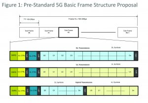
Figure 1 (above) shows one of the pre‑standard 5G frame structure proposals. Short transmit time interval (TTI) in the order of 100µs-200µs, 10 times smaller than 1ms TTI in 4G LTE with fast Hybrid ARQ acknowledgements, is being considered to reduce system latency.
Front-loaded demodulation reference and control signals enable frame processing while the frame is being received, as opposed to waiting to buffer the complete sub-frame.
Frame structure is also designed to simplify and speed up fast scheduling requests on a sub-frame basis.
For this reason, compute required in 5G baseband designs, compared to 4G LTE systems, jumps up significantly to process the sub-frame within one TTI.
5G is expected to support a flexible frame structure to adapt to different uses and application requirements such as packet length and end-to-end latency. Two sub-frame scaling methodologies with a flexible number of symbols per sub-frame and variable sub-frame lengths are under consideration. A hybrid scheme is also possible.
Both methodologies support multiple transmission types (downlink, uplink, and hybrid).
Sub frame duration and sample rate remain the same as defined for the baseline 5G numerology. Flexible frame structure has implications for physical (PHY) layer implementation.
FFT lengths and cyclic prefix may vary on a symbol-by symbol basis. The number of symbols, OFDM subcarriers per physical resource block and QAM symbols may vary on a sub-frame basis, with a variable guard period position and length. This significantly increases the complexity of physically implementing 5G.
The most expedient way to build 5G systems, at least in the early years, would be to leverage programmable FPGAs and SoCs to scale up and change systems as standards evolve, mature and to adapt implementation schemes based on the performance measurements in the field.
Opportunities in MIMO
MIMO techniques are well suited for centimeter (3GHz-30 GHz) and millimeter (30GHz-300GHz) frequencies, an inexpensive and underused spectrum resource that is available in large contiguous chunks. At higher frequencies, the transmitted signal experiences higher propagation loss.
However, narrow pencil beams that are possible at higher frequencies result in large antenna gains that compensate for the high propagation loss. In addition, as the carrier frequency gets higher, the antenna elements get smaller. With this, it is possible to pack more antenna elements into a smaller area.
For example, a state‑of‑the-art antenna containing 20 elements at 2.6GHz is roughly one meter tall. At 15GHz, it is possible to design an antenna with 200 elements that is only 5cm wide and 20cm tall.
With more antenna elements, it becomes possible to precisely steer signal transmission towards the intended receiver. Since systems are concentrating the transmission in a certain direction with many such beams in a system, coverage and capacity is significantly improved.
The 5G NR (new radio) specification support sup to 16 layers of MIMO. 5G systems intend to support rapid re-configurability of user resource allocation on a per TTI basis for higher spectrum utilisation. This has a compounding effect on the system complexity when supporting multiple MIMO layers.
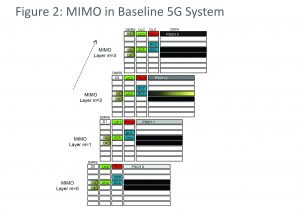
Figure 2 (right) depicts an example of user resource allocation in a 5G MIMO system. Time division duplex (TDD) helps to ease 5G massive MIMO implementation where channel state information is determined using channel reciprocity. This approach does not account for non-linearities in customer premises equipment or terminals.
Basestations must be agile
It is important to point out that in a 5G basestation, terminals are expected to keep track of multiple beams and to prompt the basestation periodically for resource allocation on the best beam for uplink data transmission. Channel state information needs to be re-computed as the user equipment terminal switches the beam.
In order to create such complex systems, it is important to incorporate sufficient flexibility and programmability to be able to adapt the implementation to achieve the desired performance with different terminals.
5G systems are typically expected to have up to 64 antenna elements for >6GHz deployments. Higher numbers of antenna elements are feasible above 6GHz. Digital beamforming is likely to be used in <6GHz frequencies (done in baseband) and hybrid schemes using a combination of digital and analogue beamforming for deployments in higher than 6GHz frequencies.
Massive MIMO system configurations comprising 64 or more antenna elements result in a significant increase in complexity and cost for supporting large numbers of active radio signal chains and pre‑coding computation in L1 baseband for digital beamforming.
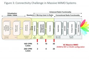
Connectivity requirements increase sharply between baseband processing signal chains and remote radio heads. To realise these systems economically, it is necessary to integrate layer 1 baseband signal processing – or a portion of it – with the radio. Such a functional split in the future may lead to network nodes where L1-L2 and radio functions are co-located.
Figure 3 (right) depicts connectivity requirements for 64 antenna element massive MIMO at various system functional boundaries underscoring the need for colocation of L1 with radio.
The scope of 5G is fairly broad and the industry community is submitting hundreds of proposals resulting in prolonged deliberations. Simulations of proposed algorithm and network configurations are good but not sufficient.
Proof of concepts and pilot field trials and testbeds are critical to
evaluating these proposals. This is making it difficult for standards bodies to review them all.
There is mounting pressure in the market to release the 5G specification sooner. Some operators are not happy with pushing massive machine type communication (mMTC) and ultra‑reliable low latency use case (URLLC) standardisation to a later phase, which is expected to complete in late 2019.
3GPP has selected low density parity check (LDPC) for data and Polar code for enhanced mobile broadband. For mMTC and URLLC use cases, LDPC, Polar, and Turbo codes are under consideration, but the industry will have to wait longer for conclusions on these. In many cases user terminals as well as 5G basestations are likely to support multiple 5G use cases, which makes it challenging and expensive to design baseband codecs.
Operators are not clear about how 5G will be commercially deployed and which uses will come to the forefront when it is. Fixed wireless access for the last mile fibre replacement and smart cities are the two leading contenders.
Vertical industry integration using URLLC, automated transportation, etc. will take longer to emerge from labs and restricted field trials to broader market adoption.
5G systems will need to build in sufficient flexibility and programmability to enable the fine tuning and evolution of system functions as it adapts to changing market realities.
[ad_2]
Source link


