
[ad_1]
If you are an electronics professional, this is is probably not for you….
I am assuming the circuit has been designed, and you are making a pcb, although the same concepts work with prototype boards.
You should know:
Getting a project into a suitable box so that it is properly useful takes as long as making and soldering the PCB, or longer.
If you have a quicker way, please comment below.
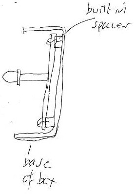
 ‘Sandwich’ construction (right) is your friend – see diagram – where spacers are used to fix the pcb to the inside of the box lid.
Anything in the user interface – leds, switches, and even connectors – go through holes in the lid and are soldered last – more of this later.
On the subject of spacers, this spacer is threaded to take 3mm screws, while a narrower type designed for 2.5 or 2mm screws will take up less room and will be strong enough. Some spacers have an un-threaded hole for ‘self-tapping’ screws.
 Standard construction (right) is also OK, using mounting bosses included in the box, but getting led leg-length right is more tricky.
Picking a box
Before you start the pcb lay-out, decide which box you are going to use. If you are really unsure of box size, quickly laying out the parts in a rectangle can help estimate necessary size.
Either chose a big box you know it will all fit into, or a smaller box and be prepared to repeat the process below.
As a re-design doesn’t take long, consider the smaller box in a choice, or the larger one if there is any point-to-point with flying leads inside.
If you have access to 3D printing – what a luxury – sizing is going to be a co-design project – do remember to include screw bosses, slots, or some other pcb mounting.
Battery note
Aside from coin and button cells, batteries are bulky. If you need them, think early. Attach them (or their holder) firmly to the inside of the box (or buy a box with a built-in holder). If there is a heavy battery on the pcb – more mounting points.
Accurately measure the box to decide exactly what size and shape of pcb is needed, and accurately find the position of the mounting holes.
TIP: if you get a box from Maplin, they are frequently supplied by Hammond (for example).
Hammond provides a drawing for each box, which includes drawing of the biggest pcb that will fit, with all mounting hole locations marked.
Here are links to quite a few Hammond boxes.
Before anything else in the pcb design package, use the design package to draw an accurate the outline of the intended pcb. Include mounting hole positions, and a ‘keep-out’ circle around each screw hole as wide as the screw head, spacer or boss. Including these lines in copper on the final pcb will help diy cutting and drilling.
Now lay out the board, putting leds, switches and other user-interface parts down first in their correct position.
At this point, you may find you cannot fit all components and tracks on the pcb. If so, either:
- Find smaller components
- Find a bigger box
Once the pcb is finalised, make it using you favourite technique, or get it made.
Important: Don’t inhale the dust from glass-reinforced pcb – hold a vacuum cleaner near when drilling and sawing.
Solder the components in, except those going through the front panel.
To drill the holes in the box for the leds and switches (and spacers if using sandwich construction), print out the pcb pattern on paper, accurately stick it to the box lid, then drill through the centre of the components on the print.
Finish sandwich construction by:
- Push the leds and other user-interface components into the front panel hole
- Thread the pcb onto the front panel component legs
- Do up the pcb mounting screws
- Solder the legs of the front panel components
Now the pcb can be un-screwed and re-attached many times, and the front panel components will always fit in their holes.
Random tips
- Avoid flying leads between components and the pcb where possible, they take up SO MUCH room, and can snap off later – so no leds attached to the box with long wires to the pcb.
- For indication, 3mm leds are far neater than 5mm leds. In general, use wide angle leds for indicators.
- For fewer holes, leds (including surface-mount) inside a transparent box can work.
- Tall ‘tact’ switches can poke though the front panel for simple push buttons. They come in different heights – here is a very tall one.
- Do not use thin tracks on your first pcb (0.5mm or 0.02inch minimum). The risk is etching away or detaching during soldering.
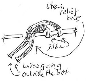 If wires have to leave the box, and you have space, to reduce strain and movement at the solder joint make a plain hole in the pcb and thread any flying leads through that as well as soldering the end (see diagram). If you do not have space, make sure the wires are firmly supported and clamped as they leave the box – or use a connector.
- If you mount a connector directly on the pcb, be aware it will gets LOT of force when less caring folk either ram in the plug, drop the box, or drag it around by its wires, so put plenty of glue around the connector where it meets the pcb (after testing!) or use a connector with a substantial solder-down frame.

The End, roll credits.
[ad_2]
Source link