
[ad_1]
These are inside just about every ‘quartz clock’ and are powered by a single AA cell.
Apparently, the pcb inside provides narrow pulses to two outputs, across which a high-resistance solenoid is wired. This solenoid pushes the hands around via mechanical stuff.
 Anyway, from each output comes a pulse once every 2s (0.5Hz), but they alternate, so there is one pulse every second.
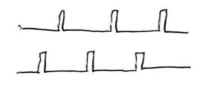
 It looks like, depending on the particular module type, these pulses are either positive going or negative-going – see diagrams.
Caveat emptor: From now on, everything is educated (I claim) guesses (for certain).
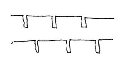
Use a scope to see which pulses you have, or estimate: put a voltmeter between the negative terminal of the battery and either of the outputs.
- If you have positive-going pulses (right above), it will read about 0V
- If you have negative-going pulses (left above), it will read about 1.5V
To check, take readings from the positive terminal of the battery to an output
- If you have positive-going pulses (right above), it will read about 1.5V
- If you have negative-going pulses (left above), it will read about 0V
I am going to guess that these pulses run pretty much from rail to rail of the ~1.5V battery and, so that coil current can flow, I surmise that when one output is making a pulse, the other output is clamping its end of the coil to the opposite rail.
If you want a 1Hz pulse train, you need to combine the two 500ms shifted 0.5Hz pulse trains.
I have seen quite a lot of circuits using diodes to add the pulse trains, throwing away ~0.6V of the available 1.5V, with following transistor buffers using some unusual transistor configurations – at this point I apologies if these configurations are used for some subtle reason I am too daft to spot.
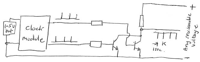 Instead, here are a couple of far more conventional circuits penned in two minutes at Electronics Weekly Towers (one for each of the two situations above) that I think fit the bill as non-cranky ways to combine the pulse trains – both of which I have subsequently found on the web, although they are far less commonly that diode+odd buffer circuits.
 They need either a pair of npn or a pair of pnp transistors, and can be connected to any reasonable voltage, including the 3, 3.3 or 5V rail of the Arduino you happen to be using.
Almost any transistors of the appropriate polarity can be used.
Resistors can be calculated, although you will not go far wrong with 10kΩ in all three positions.
For simplicity, if you are feeding this into an Arduino and counting, why not miss out one of the transistors and its base resistor, which will yield one pulse every 2s, and count slower using that.
Some odds and sods
This is probably going to work best (the battery last longer) if you disconnect the coil/solenoid – so the hands will no longer work.
Some clock modules apparently use ceramic resonators rather than crystals, so maybe get a superior clock if accuracy is important. A quick poll around the office decided that most reasonable wall clocks are accurate to better than 5min in a year.
If less accuracy is acceptable, then just count the microcontroller clock – even the internal RC clocks of PICs are good to ~1%.
If more accuracy is required, buy a second-hand atomic clock (really), or use an off-air standard such as one hooked to the 198kHz Droitwich transmitter (Radio 4 long wave) or one hooked to GPS – these off air devices are a few hundred quid, but some GPS modules for tens of quid (for example, which has 1Hz out) seem to have a frequency output.
Google around a bit and there is at lease one kit for a Droitwich receiver, plus some circuits – most of which can be simplified because they have extra circuits to get a stable 10MHz signal from the lower frequency received signal.
Some (‘self setting’) wall clocks have in-built radio receivers linked to atomic-based time references, and those with hands might well have a similar coil driving scheme to the quartz clocks, so the circuits above could be used – although beware extra/missing pulses at the switch-overs between winter and summer times.
Running off an alkaline cell should give at least a year’s operation, but if you absolutely have to eliminate the battery you could create a 1.5V rail to run the module. People have done this using a couple of diodes as a shunt regulator~1.3V – which would have to be fed through a resistor from the same rail that feeds the output (collector) resistor – which differs in the two cases.
[ad_2]
Source link