
[ad_1]
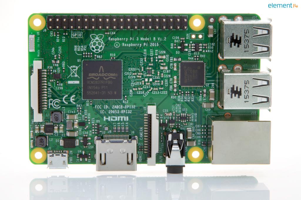
Raspberry Pi 3
Having spent a while recently trying to fix an ancient oscilloscope, it occurred to me that it might be quicker to make one from a Raspberry Pi.
After all, the Pi accepts keyboard and mouse connections, has a capable graphics processor, and has a choice of graphics outputs: HD-quality HDMI for a separate monitor, or a DSI output that matches with the Foundation’s own 800×480 7in touch screen – onto whose back a Pi can be mounted.
I quickly discovered that is the other end of the scope signal chain where the challenge lies: bridging the gap between the Raspberry Pi and a scope probe BNC connector, without loosing signal fidelity, and with sufficient speed.
There have been some heroic efforts to do this, and some innovators have really pushed the boundaries of what is possible, including clever software manipulation that achieves 10Msample/s though Raspberry Pi’s 40pin GPIO interface. And there are plenty of folk that have managed to hit 1Msample/s for a single channel.
But what would it take to turn it into a real scope – say one with 10 or 20MHz of bandwidth?
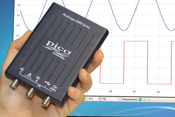 Who better to ask than Pico Technology, the UK-based PC oscilloscope firm that already makes a 10MHz USB scope-in-a-box (the 2204A, pictured) that will plug into Raspberry Pi for under £100 – half the price of some bare-board USB scopes.
So, how easy would it be to convert a Raspberry Pi into a competent 10MHz scope? Perhaps by making a custom add-on board, knows as a HAT – hardware attached on top – in the world of Pi.
Possible, but not trivial, was the response of Pico’s sales and marketing manager Trevor Smith.
What stops it being a simple case of putting an ADC on a PCB is data bandwidth.
“The industry rule-of-thumb is having a sample rate of five times the maximum analogue bandwidth,” said Smith, “so for 10MHz bandwidth you need an ADC running at 50Msample/s/channel, which is 100Msample/s x 8bits for two channels – not trivial.”
And this is not going to pass easily across the GPIO or any of the USB channels on a Raspberry Pi.
“If every time you made an acquisition you sent it up the USB cable, the USB cable would become a bottleneck,” said Smith.
At this point, you wither work back from the data bottleneck and accept what ever sample rate that makes possible, or you do what USB scope makers do: use local digital signal processing to compress data before it has to go though the USB cable – a technique that could be applied to a scope HAT, said Smith, regardless of which Pi interface was used.
One of the things that is important in an oscilloscope is update rate. The user needs to see a lively display when the signal is changing, but there is no need for updates faster than the user can perceive.
This means that the system bottleneck is sufficiently wide if it can pass data at the maximum useful rate. “USB is fast enough for humans,” said Smith.
In most USB scopes, on-board data processing is handled by an FPGA – this is true of Pico’s products – and what goes on in that FPGA is a key item of scope manufacturer intellectual property, but for basic operation it doesn’t have to be that complicated.
Its job is to mediate between front-end ADCs, local memory and the data pipe: directing data from ADCs to RAM as fast as the selected sweep rate and memory capacity will allow, and directing data from RAM to the host via the chosen compression process.
Compression?
“The FPGA is sending a result summary to the PC to display,” said Smith. “Say you have thousands of points, and don’t need thousands of points on display – FPGA works out what needs to be sent – you wouldn’t want 10,000 points time after time after time.”
According to him, a simple form of compression is sending min-max pairs. If there are 100,000 samples in the memory, but the display is only 1,000 pixels across, blocks of 100 samples are scanned to find the minimum and maximum sample value in the block, and only these two numbers are sent.
The scope software running on the host then displays a vertical line between min and max value for that location along the horizontal time graph.
“If you had simply sent one in every 100 points, you would miss glitches, and a major function of a scope is to look for glitches,” said Smith.
Refreshed at 50Hz – 50 traces one over another – the user gets a lively display.
“The update rate is determined by performance of FPGA, not so much the USB,” said Smith, adding that, beyond 10MHz, memory bandwidth between FPGA and memory has to be maintained. “A lot of effort goes into designing the memory interface,” he said.
As well as removing the need for fast interfaces, the on-board FPGA also reduces the host workload as it now only has to control the FPGA and display waveforms. That said, the host computer can get involved when things like fast Fourier transforms (FFTs) need calculating for a frequency domain display, when all the data in the sample memory might need shifting through the data pipe, stopping real-time operation temprarily.
If the scope hardware is asked to act as a digitiser – “You might want to throw data at MATLAB,” said Smith – the FPGA has the job of arranging the fastest real-time operation possible within the limits of the connecting bus – although this is probably beyond the needs of a Raspberry Pi scope HAT. For professional-grade PC scopes, USB 3 interfaces can help here.
On the other side of the input ADC or ADCs, depending on whether multiplexing is used for multiple channels, each channel gets an input attenuator and input amplifier.
“At low frequency, the attenuator can be done with resistors plus capacitors quite readily,” said Smith. “If trying to achieve 1MHz or more, you have to start matching characteristics of the front end attenuator with the signal chain.”
There would have to be ac/dc switching and attenuation adjustment, some of which can be done with electronic switches, although a surprising number of scopes still use relays (bi-stable types to save power) in critical positions like the ac/dc coupling switch.
All this should be possible in the area of a HAT, even though there will almost certainly be at lease one trimmer capacitor per channel to tweak response.
“You are trying to achieve pretty good linearity out to the bandwidth of the scope,” said Smith. “You need to pay attention to the linearity of the whole signal chain: attenuator, amplifier and ADC. Frequency response and pulse response don’t always run together. You can end up with fairly good flatness, and then you put a pulse in and get all sorts of ringing and over-shoot.”
And a decision will have to be made to create a local negative rail or to shift the incoming signal somewhere between 0 and 5V.
On the subject of grounding: “for us, the signal grounds need to be bought out onto proper signal connectors – BNCs.
Getting solid connections between the input socket, attenuator, amplifier (integrated or discrete) and ADCs helps keep down noise.
“You want a front end that is low-enough in noise to be compatible with resolution of the scope you are trying to build. You don’t want more than half a division of noise on the screen, on most sensitive range,” said Smith. “We have 10 divisions vertically in the display and the most sensitive range is 1mV/division, which is 10mV/screen, so you would want <500uV of noise – most people’s 8bit scopes struggle to meet that, but it is a nice goal.”
With two side of the PCB to play with, a Raspberry Pi HAT with enough performance to call itself a proper 10MHz scope looks distinctly plausible.
Unless someone delves into the Broadcom chips deeply enough to unlock the secrets of Pi’s 2Gbit/s MIPI CSI-2 camera interface, and find it borrowable, there is going to have to be an FPGA on that HAT, and developing suitable firmware is going to be a labour of love. Analogue-wise, the devil will be in the detail.
It would certainly be easier to buy a PicoScope 2204A.
[ad_2]
Source link