
[ad_1]

Some perspective
Despite the hype behind some famous virtual-reality goggle brands, the problems they have solved are as nothing to those augmented-reality firms are up against.
By their enclosed nature, the optics within VR goggles never have to compete with sunlight and, as they will almost never be worn outdoors, street fashion has no impact on their appearance – they can be bulky.
As such, even the most expensive VR goggles are little more than a pair of ~50mm LCDs (or one long one), in a light-proof box that also supports a lens for each eye to focus the LCD image onto the retina.
At one end of the market, Google cardboard calls for a phone to provide images and motion sensing, and two simple lenses. And at the other end, the money goes into far better lenses and vastly improved motion sensing.
There is nowhere to put a 50mm LCD within a pair of augmented-reality glasses, so the challenge becomes how to get images from a pair of microdisplays onto the retina, in focus, and at an intensity that can compete with light landing from the outside world.
Reflective (mirrors) or refractive (prisms) optics can do it, for a certain 3D physical envelope, but WaveOptics of Abingdon is amongst the few companies aiming to do it with diffractive optics – a technology which can squeeze most of the optical chain into a thin sheet of glass.
While refraction and reflection are fairly intuitive, at least at the highest level, diffractive optics can boggle the mind – and, as such, a significant part of the company’s team is either mathematicians or optical modellers, according to David Grey, who founded the company with Sumanta Talukdar in 2014 on shared expertise.
 What is it and what does it do?
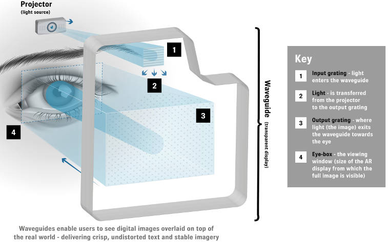
It is an optical waveguide – a shaped piece of modified flat glass with an input area and an output area.
Take a projector, explained Grey, and focus its image on a wall three metres away.
Interrupt the projector by placing the input area of the glass in its beam.
Now the image no longer appears on the wall, but if you put your head next to the projector and peer through the output area of the glass at the wall, the image is there, apparently focussed on the wall.
The waveguide has taken the beam, moved it sideways through the sheet of glass, and emitted it back at the viewer in a way that makes it appear focussed 3m away.
“Our waveguide maintains all of the angular and chromaic qualities of image,” Grey told Electronics Weekly.
What happens within the waveguide is ‘two-dimensional pupil expansion’.
When light hits the input area – which is only a few mm across and therefore compatible with micro-projectors – is that a simple diffraction grating turns the light through 90° into the sheet, towards the exit area.
It then bounces along between the two glass/air interfaces, constrained by total internal reflection, until it gets to the exit area.
Here, a patented regular hexagonal pattern of dots on one surface, constituting a photonic crystal with two diffeaction gratings crossing one-another, causes wave interactions that spread the concentrated light out across the exit area, as well as turning it through another 90°, back towards the viewer.
Whatever is going on inside the glass, the only important thing, said Grey, is that the angle at which light entered the glass originally is maintained exactly when it leaves the glass. Providing this happens, the system works.
As it happens, it is irrelevant how many times internal reflection occurs, said Grey, who also pointed out that an individual ray of light, from a single pixel in the original image source, for example, will emerge from several places on the exit area, in a regular array.
While the WaveOptics system has expanded the light from input to output in two dimensions simultaneously, said Gray, alternative diffractive optics aimed at the same application expand it in one dimension, turn it within the glass though 90°, then expand it in the other dimension (see diagram) . The additional 90° rotation requires extra glass area reducing the area available for optical output.
The area available for output is important if fiddly adjustment to compensate for each user’s eye-to-eye distance is to be avoided.
When using the system, the receiving eye will get a perfect image if it is aligned with the centre of the output area. As the eye moves sideways or up and down, at some point in each direction the image will deteriorate until it is unacceptable.
Stringing all these points together forms a shape called the ‘eyebox’.
Cheap binoculars have a small eyebox – you are forever fiddling with the width adjustment to get a good image in both eyes.
The challenge with AR glasses is to get an eye box large enough that most people can use them without adjustment, said Grey, requiring a large eyebox.
Another important parameter is the apparent size of the augmenting image – can it fill enough of the scene to be useful. If the AR glasses can ‘project’ over a larger angle, then they can fill more of the visual field.
It transpires that, for a given amount of light entering the system, there is a trade off between eyebox area, angular field of view and the perceived brightness of the image.
According to Grey, his waveguides can achieve a usable eyebox size and brightness with a 40° field of view with readily available glass, increasing to 55° if more exotic high refractive index glass is used. He compares this with 35° achieved by a competitor using high-index glass because they use separate x and y expansion and ligh tis lost in the additional 90°in-glass turn. “Our output bigger for a certain size of glass.” he said.
There is an inevitable spectral bandwidth limit is diffractive 2-d pupil expansion systems. In WaveOptics’ case, it has to stack two glass waveguides, one to cover blue and part of green, and the other for the rest f green and red. Another option, used by some aiming at the same market, is to use three, one for each red, green and blue.
Whist two or three waveguides are needed, manufacturing is sraight-forward according to Grey because no sub-wavelength tolereaces are involved. “They don’t need to be actively alligned, they only need normal mechanical tolerances, so you can simply assemble them,” he said.
However efficient the optical system is, light is always going to be wasted by creating that big convenient eyebox, because only a fraction of it is used by any particular individual.
Which means the micro-projector for each eye needs to produce plenty of light.
Compactness is essential – but against this the projectors at least need a collimating lens between their display and the 2-D pupil expander so that light is lagely parallel which it enters, containing only the subtle angular information that will produce the final image. The current favoured layout is to mount the projectors sideways above each eye, with a mirror or prism to couple the image beam into the expander.
To make the image, there are two incumbent technologies, and one waiting in the wings if it can be made to work.
The need is for a bright energy-efficient technology with sufficient pixels/degree to give acceptable resolution in the desired image – more if the image has that desirable big field of view.
The incumbents are both reflective: Versions of TI’s now venerable digital mirror device (DMD) which uses an array of micro-machined mirrors to direct light from red, green and blue LEDs; and liquid-crystal-on-silicon (LcoS) shutters which also need three LEDs to provide light.
“We have used TI DMD and LcoS – our modules can be designed for either – and we have made modules with both,” said Grey. “Without the projectors running exactly warm, we get an image you can view in daylight. If they have to work in bright sunlight, many companies are putting a tint in the glass.”
The potential new-kid-on-the-block is micro-LED. This emissive technology would simplify the projector as there would be no need for separate illuminating LEDs, and no need for the bulky – in glasses frame terms – optical system that connects those LEDs to the reflective display.
But can anyone make a suitable LED display at the right price?
It has to be bright, with very small – around 10 micron red-green-blue – pixels, and be monolithic because it is unlikely anyone could place so many separate tiny LED die onto a substrate.
UK-based Plessey claims to have a roadmap that takes it to such a high-brightness monolithic full-colour LED micro-display.
It is a company that has already demonstrated a combination of metalisation layers and multiple isolated GaN LED die on a silicon substrate, and whose chip-making experience means an active matrix in the underlying substrate is manageable.
The technology is based on its in-house GaN-on-silicon blue LED platform, plus a technique for depositing blue-to-green phosphor on every third micro-LED and blue-to-red phosphor on half of the remainder – producing the RGB emissive matrix.
“A micro-LED display, if it became available, would be the optimum in terms of form factor and performance,” said WaveOptics’ Grey, “if it was small enough and reliable.”
Manufacturability is the last attribute Grey claims. “You have to make sure your manufacturing process is scalable, you have to make many millions,” he said.
His company is modifying a sheet of glass by contact-printing patterns on its surface with UV-cureable resin. “The replication process is ‘contact print, cure and separate’, said Grey. Who said WaveOptics is now getting 11 waveguides per glass wafer and this year intends to scale up to “tens of thousands”.
[ad_2]
Source link