
[ad_1]

If you park in a garage, you’re probably familiar with the problem: how far do you pull your car into the garage to make sure there’s room in front for whatever is there and enough space behind so the garage door will close?
Some people suspend a tennis ball on a string from the ceiling and stop at the point when the ball meets the windshield. That works fine, but the ball is a pain to set up and adjust, and it often gets in the way if you want to use the garage for something other than parking the car. Arduino offers a better solution.
This Garage Parking project is the electronic version of the classic tennis-ball-on-a-string device, only better. The Garage Sentry accurately detects when your car reaches exactly the right position in the garage and sets off an alarm that blinks so you know when to hit the brakes.
It is also possible to modify this basic Garage Sentry into a deluxe version (pictured) that alerts you when you’re getting close to the perfect stopping point.
Required tools
This project doesn’t require many tools or materials, but you will need the following tools for both the standard and deluxe versions:
- A drill with a 3/8-inch or 1/2-inch chuck (powered by battery or with 110/220V from the wall)
- Drill bits for potentiometer (9/32 inches), power input (1/4 inches), and LED (3/8 inches)
- Soldering iron and solder
- Tapered reamer
- Screwdrivers (See the Introduction for screwdrivers you should have on hand.)
- Pliers (I recommend needle nose.)
- 28- or 30-gauge hookup wire
- (Optional) Wire-wrap tool and wire
- (Optional) 1/4-inch tap
Parts list
You’ll need the following parts to build the basic Garage Parking Sentry:
- One Arduino Nano (or clone)
- One HC-SR04 ultrasonic sensor
- Two high-intensity LEDs (>12,000 MCD)
- Two 270-ohm, 1/4 W (or more) resistors (to limit current to the LEDs)
- One 20-ohm, 1/8 W potentiometer
- Two NPN-signal transistors rated for a collector current of at least 1.5 A (I used ZTX649 transistors.)
- One enclosure (I recommend a blue Hammond 1591 ATBU, clear 1591 ATCL, or something similar.)
- (Optional) One 0.80-inch aluminium strip for mounting bracket
- (Optional) Two 1/4-inch × 20-inch × 3/4-inch bolts with nuts
- One section (approximately 1 inch × 1 inch) perforated board (can include copper-foil rings on one side)
- One 3.5 mm jack for power
- Two 2-56 × 3/8-inch screws and nuts
- Two additional 2-56 nuts to use as spacer
- One 9V, 100 mA plug-in wall adapter power supply (Anything from 7.5V to 12V DC at 100 mA or upward should work well.)
- One piece of double-sided foam tape about 3-inches long
- One LM78L05 (TO-92 package) regulator (for the breadboard build only)
Because the basic version doesn’t require a lot of additional components, I suggest building the circuit on a standard perforated circuit board instead of a shield. To power your circuit, you can use a 9V, 100 mA wall adapter plugged into a 3.5 mm jack. You shouldn’t need an on/off switch.
I used a Magnavox AC adapter, but any similar power supply with a DC output from 7.5V to 12V should work. These are readily available online and cost from under $1.00 to about $3.00.
Be sure to use two bright LEDs that are clearly visible, even when a car’s headlights are on. Bright LEDs range from 10,000 MCD (millicandela) to more than 200,000 MCD. The brighter, the better; just remember that brighter LEDs require more power, so the current-limiting resistor will need a higher power rating for the brighter lamps.
The 270-ohm current limiting resistors result in a current drain of about 30–40 mA each with the 12,000 MCD LEDs I used at 5V. (Remember that power equals volts times amps, or P = VI, so at 40 mA and 5V, you’d have 0.20 W.)
It’s best to use a 1/2 W or greater resistor even though you can easily get by with a smaller value – as I did with 1/4 W – because the LEDs are on only intermittently.
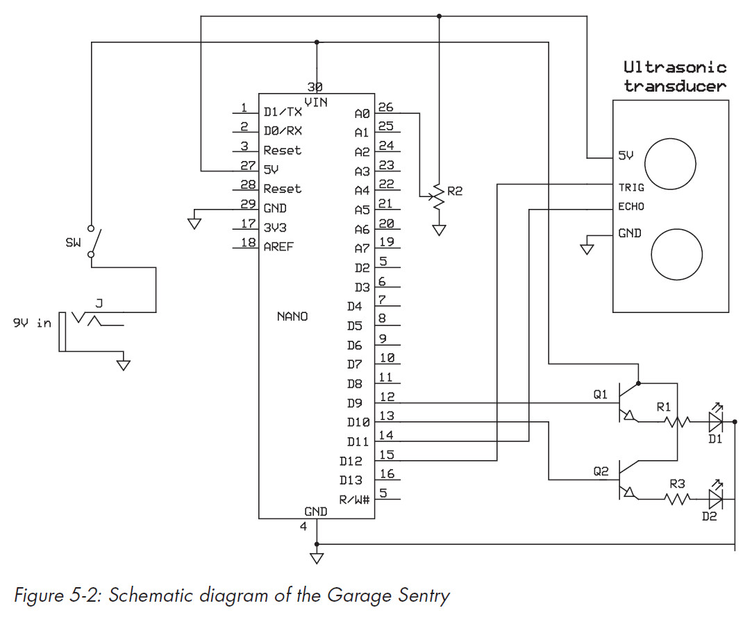
The schematic
Figure 5-2 shows the schematic for the Garage Sentry. R1 and R3 are the 270-ohmresistors for the LEDs and should be 1/4 W or larger. If a higher wattage resistor is not available, you could place several resistors in parallel to gain the required wattage. First, find the right resistor value with the formula:
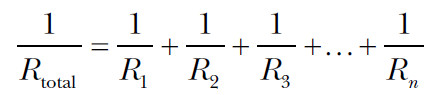
You can also use an automatic calculator, such as the one at www.1728.org/resistrs.htm, which is a lot easier than doing the maths yourself.
To avoid extra calculations, select resistors of the same value. This way, the same amount of current flows through each one. For example, two 1/8 W resistors in parallel will give you a 1/4 W value.
If you do use resistors of different values, you will have to calculate the current flowing through each and the total dissipation. This schematic also leaves you with room to customize your alarm. While this version of the project uses LEDs to create a visual alarm, with a slight modification, you can easily create an audible alarm as well. Simply replace either the red or blue LED with an audible device, such as a Sonotone Sonalert, and the alarm will sound. To replace an LED, you would need to connect the Sonalert across that LED’s connections; just make sure to get the polarity correct. Alternatively, you could keep both LEDs and add an audible device for a third warning.
NOTE: In this project, the Nano takes advantage of its on-board voltage regulator, which is why there’s no external regulator in the schematic.
Basics of calculating distance
This project measures the time it takes for a sound to originate, bounce off an object, and be received back at the point of origin, and it uses that time to calculate the distance between the object and the sensor.
The basic distance calculation is not much different from determining the distance of a storm by counting the seconds between a lightning flash and a thunderclap. Each second represents a distance of 1,125 feet, or about 0.2 miles. Given that sound travels at 1,125 feet per second in air at sea level, if there’s a five-second delay between a lightning flash and the thunderclap, you can determine that the storm is roughly a mile away.
In the case of the Garage Sentry, once you know how long it takes for the sound to make a round trip and know the speed of sound, you can calculate the distance according to the time-speed-distance formula:
Distance = Speed × Time
How the Garage Parking Sentry works
This project takes advantage of ultrasonic sound, which, unlike thunder, is above the hearing range of most individuals. If your hearing is good, you can detect sound ranging from about 30 Hz to close to 20 kHz, although hearing attenuates quickly above 10 kHz or 15 kHz.
NOTE: For reference, middle C on the piano is 261.6 Hz. Young children (and most dogs) can often hear high frequencies, but hearing, especially in the upper registers, deteriorates quickly with age.
The ultrasonic transceiver module used in this project sends out pulses at a frequency of about 25 kHz and listens for an echo with a microphone. If there is something for the signal to bounce off, the system receives the return echo and tells the microcontroller a signal has been received and to calculate the distance. For the Garage Sentry, the unit is placed in the front of the garage, and the signal is sent out to bounce off the front – or rear if you are backing in – of your vehicle.
To calculate your car’s distance from the ultrasonic transceiver, the Arduino measures the time it takes for the signal’s round trip from the transceiver to the target and back. For example, if the Arduino measures a time of 10 milliseconds (0.010 seconds), you might calculate the distance as:
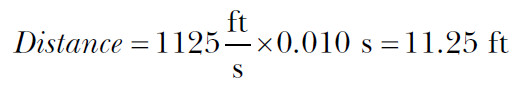
Ah, but not so fast. Remember the signal is travelling to the car and then back to the microphone. To get the correct distance to the vehicle, we will have to divide by two. If the controller measures 10 milliseconds, then the distance to your car would be:

The HC-SR04 ultrasonic module sends out a signal at the instruction of the Arduino (see Figure 5-3). Then, the sketch instructs the transmitter to shut down, and the microphone listens for an echo.
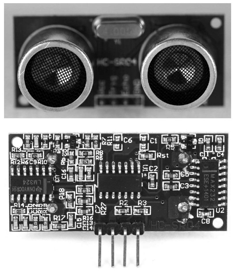
Figure 5-3: The ultrasonic sensor module. The back of the module (bottom) has connection terminals at the bottom.
If there is an object for the signal to bounce off, the microphone picks up the reflected signal. The Arduino marks the exact time the signal is sent out and the time it is received and then calculates the delay.
The HC-SR04 module is more than a speaker and microphone, though.
The module includes transducers – a loudspeaker and mic – and a lot of electronics, including at least three integrated circuits, a crystal, and several passive components. These components simplify its interface to the Arduino: the 25 kHz tone is actually generated by the module and turned on and off with the microcontroller. Some of the components also enhance the receiver’s, or the microphone’s, sensitivity, which gives it a better range.
The range of the HC-SR04 ultrasonic transducer is approximately 10 to 12 feet. The returning signal is always a lot weaker than the transmitted signal because some of the sound wave’s energy dissipates in the air (see the dotted lines in Figure 5-4).
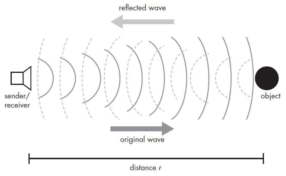
Figure 5-4: In this project, sound is transmitted from a sender, bounces off an object and is received.
The arithmetic to calculate the distance between the sender and the object is not difficult. You take the number of microseconds it takes for the signal to return, divide by the 73.746 microseconds it takes sound to travel an inch, and then divide by two because the signal is going out and coming back. The full arithmetic for this appears later in “Determining Distance” on page 141.
The sketch provides a response in inches or centimeters depending on your preference. We’ll use inches for setting up the distance for the alarm, but converting to centimeters simply requires a remapping of the analog input and setting the numbers a bit differently. The sketch also does the basic arithmetic for determining the centimeter measurement for you.
With the high-level overview out of the way, let’s dig in to how you’ll wire the Garage Sentry… To be continued.
[Part 2 will follow separately]
The author
The author, Warren Andrews, has done technical consulting for corporations such as Motorola and GE, and written about electronics for more than 30 years, for publications such as EE Times, Electronic Design, Computer Design and RTC Magazine.
Arduino Playground details
Title: Arduino Playground, Geeky Projects for the Experienced Maker
By: Warren Andrews
Publisher: No Starch Press
Date: March 2017
Price: $29.95 (print), $23.95 (Ebook)
Pages: 344
ISBN: 978-1-59327-744-4
See also: Gadget Book: Arduino Playground, for experienced makers
[ad_2]
Source link