
[ad_1]
See also: How to build an Arduino Garage Parking Assistant, Part I
The Breadboard
The entire Garage Sentry fits on a small breadboard, so you can set it up, program it, power it with a battery, and walk around to test it out. As you play with it, I’m sure other applications of ultrasonic technology will come to mind.
The breadboard I assembled appears below in Figure 5-5.

It is powered by a 9V battery. Usually, you could wire the battery directly to the VIN of the Nano and use the Nano’s built-in voltage regulator. But you’ll power the Nano with a USB cable when you program and test it for the first time, so on the breadboard, you’ll set up the positive and negative rails for 5V for both the Nano and the ultrasonic module.
To avoid risking damage to the Nano or the module and avoid overcomplicating the build, I included a single-chip external voltage regulator (LM78L05) so the entire breadboard runs on 5V. Take a look at:
This is how the LM78L05 TO-92 regulator is wired up on the breadboard. Bypass/filter capacitors are not required:

Here’s a blow-by-blow list of the steps to wire the breadboard:
- First, put the ultrasonic module at the lower end of the breadboard facing out, and plug the Nano in to the breadboard, leaving four rows of connections above it.
- Make sure the positive and negative rails (red and blue stripes) on the left and right are connected properly—red to red, blue to blue. If you connect red to blue, it will cause a major problem.
- Connect the red positive rail to the 5V power supply (pin 27 of the Nano, labelled 5V). This is necessary if you are operating from the USB connector.
- Connect pin 4 of the Nano (labelled GND) to the breadboard’s blue negative rail.
- Connect VCC of the HC-SR04 transducer to the red positive rail.
- Connect GND of the HC-SR04 transducer to the blue negative rail.
- Connect TRIG of the HC-SR04 transducer to pin 15 (D12) of the Nano.
- Connect ECHO of the HC-SR04 transducer to pin 14 (D11) of the Nano.
- Insert two ZTX649 transistors into the breadboard. Select an area where all three pins of each transistor can have their own row.
- Connect pin 12 (D9) of the Nano to the base of transistor Q1.
- Connect pin 13 (D10) of the Nano to the base of transistor Q2.
- Connect the collectors of both transistors to the red positive rail.
- Connect the emitter of transistor Q1 to one end of a 270-ohm resistor.
- Connect the other end of the 270-ohm resistor connected to the emitter of transistor Q1 to a blank row on the breadboard.
- Connect the emitter of transistor Q2 to one end of another 270-ohm resistor. Connect the other end of the 270-ohm resistor connected to the emitter of transistor Q2 to another blank row on the breadboard.
- Connect the + (long end) of LED (D1) to the 270-ohm resistor and the other end to the blue negative rail.
- Connect the + (long end) of LED (D2) to the second 270-ohm resistor and the other end to the blue negative rail.
- Connect one end of the 20-ohm potentiometer to the red positive rail.
- Connect the opposite end of the potentiometer to the blue negative rail.
- Connect the wiper (centre) of the potentiometer to analog pin A0 (26) of the Nano.
You should be good to go! If you use the AC connection, simply connect it to the VCC connection of the Nano.
To add a battery connection, include the 78L05 with its centre pin to ground (negative rail), the input to the positive side of the battery, and the output to the positive rail. Connect the negative terminal of the battery to the negative rail.
The Sketch
Once the breadboard is complete, the sketch can be loaded onto the Nano. Download the GarageSentry.ino file from www.nostarch.com/arduinoplayground/.
Once it’s loaded, the unit is ready for experimentation.
The sketch for the Garage Sentry serves several functions. It tells the ultrasonic sensor to generate a wave and detects how long it takes the echo to return. It then calculates the distance based on that time and, if necessary, alerts you to stop by turning on the LEDs.
Construction
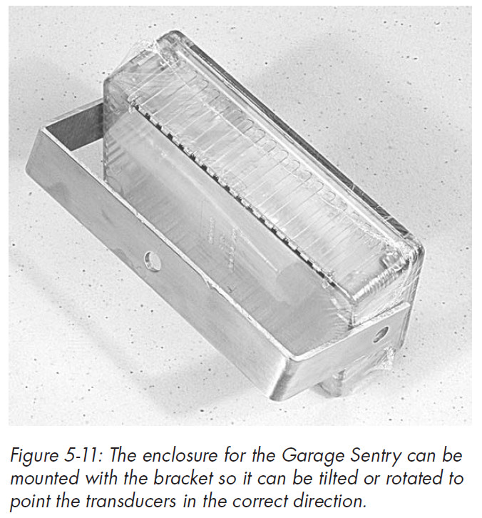
The trickiest part of the Garage Sentry is mounting the ultrasonic module on the enclosure.
Because the module can send out sound waves only in a straight line, you need to be able to adjust its direction so that the ultrasonic sensor can hit its target and receive the echo. But the module includes only two mounting holes, diagonally opposed from each other, so there’s no easy way to fasten it to a flexible mounting. We’ll tackle that first.
Drilling Holes for the Electronics
To solve this problem, I mounted the transceiver directly to the enclosure and just aimed the enclosure as required. To mount the module, drill 5/8-inch holes in the enclosure and use standoffs to hold the board securely. See the template in Figure 5-8 for drilling measurements. A PDF of the template (Transducer.pdf ) is available in this book’s online resources at www.nostarch.com/arduinoplayground/, in case you want to print it and lay it over your enclosure as a guide.
The enclosure I recommend is made of polycarbonate plastic and is less likely to crack than styrene or acrylic; however, it tends to catch the drill, so be careful.
Mounting Options
Before you stuff the Arduino, ultrasonic sensor, and perforated board circuit into your enclosure, figure out how you want to mount the Garage Sentry.
There are several ways to mount the enclosure onto whatever surface you need. You could, for example simply affix the box with adhesive Velcro.
If you don’t have a good surface and need to aim the module at an angle, mounting it on a U bracket that lets the sensors swing up and down or left and right will work.
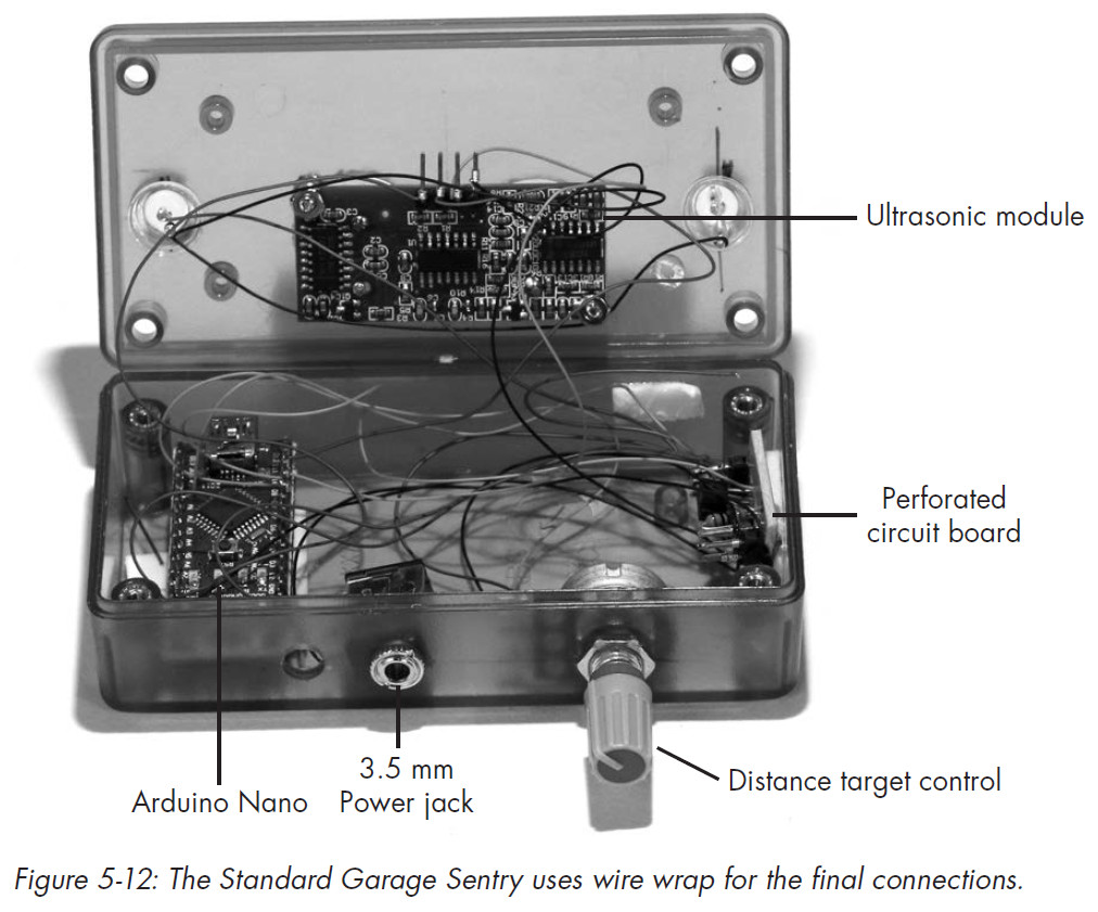
Soldering the Transistors and Current-Limiting Resistors
After testing your circuit on a breadboard and deciding how to mount the Garage Sentry, solder the driver transistors and current-limiting resistors to a small section of perforated phenolic or FR-4 predrilled board. Use the schematic in Figure 5-4 or the instructions in “The Breadboard” on page 136 as a guide to wiring and soldering the components in the perforated board.
Make the connections in the schematic, but otherwise, there is no right or wrong way to assemble the perf board. I do recommend using perforated board with copper pads for each hole to simplify soldering. Solder all the hookup wires for the power, potentiometer, Nano, ultrasonic module, and LEDs before attempting to mount the board on the inside of the enclosure.
When you’re done soldering, mount the perforated board anywhere in the enclosure where you can find room. I used double-sided foam adhesive, and it worked well. Mount the Nano, LEDs, and ultrasonic module next.
Wiring the Pieces Together
Finally, use 30-gauge hookup wire to connect the Nano, ultrasonic sensor, perforated board circuit, and LEDs according to the schematic in Figure 5-4.
Optionally, you can use wire-wrap wire and a wire-wrap tool to wire up the sections, but it is not necessary and can be expensive if you don’t already have the tool and wire. Wiring the components and fitting them in the enclosure may be a little messy, but it saves building a shield.
Finish
The completed sentry unit works flawlessly. Depending on your particular garage and where you place the unit, you might want to adjust the sketch to make the green and amber lights turn on at different distances.
The unit has been working perfectly for almost six months now, and I don’t know how I’d be able to pull my car in the garage without it.
Inspiration Behind the Garage Sentry
This project evolved out of playing with an ultrasonic transceiver module, a device that emits sound waves and then detects them after they travel to an object, reflect off that object, and travel back to the module.
The output of the module allows a microcontroller to measure the time it takes to travel to and from the object and, knowing the speed of sound, determine the distance.
To test the ultrasonic transceiver’s sensitivity and limits, I used the battery-operated breadboard version in my garage, which had enough space to move objects around for different distances. It turns out cars are great reflectors for ultrasonic energy.
From this experimentation, I was inspired to turn my test apparatus into a Garage Sentry.
See also: How to build an Arduino Garage Parking Assistant, Part I
The author
The author, Warren Andrews, has done technical consulting for corporations such as Motorola and GE, and written about electronics for more than 30 years, for publications such as EE Times, Electronic Design, Computer Design, and RTC Magazine.
Arduino Playground details
Title: Arduino Playground, Geeky Projects for the Experienced Maker
By: Warren Andrews
Publisher: No Starch Press
Date: March 2017
Price: $29.95 (print), $23.95 (Ebook)
Pages: 344
ISBN: 978-1-59327-744-4
See also: Gadget Book: Arduino Playground, for experienced makers
[ad_2]
Source link