
[ad_1]
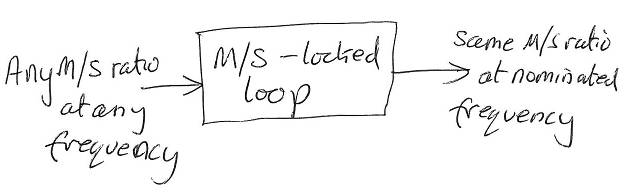
This is a thing, I propose, which would take a pulse-width-modulated waveform at any frequency, and produce a signal with exactly the same mark/space ratio, but at a nominated frequency (see ‘Why might this be useful?’ below).
It would be a bit like a phase-locked loop (PLL), which is a very useful thing for frequency multiplication, jitter reduction, frequency demodulation and narrow-band signal detection, to name but a few uses.
Those who know what a phase-locked loop is should now skip down to Mark/space ratio locked loop.
 For the un-initiated, a phase-locked loop is a circuit that can take a mystery frequency at its input, lock to it, and produce a nominated multiple of that frequency.
That multiple could be any whole number, and even fractions of whole numbers, like 5/3 times the input frequency.
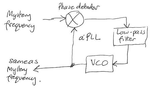 In its simplest form, the PLL produces 1x the input frequency – the same frequency – and it works like this:
A voltage-controlled oscillator (VCO) makes a frequency.
This frequency is compared with the mystery frequency in the phase detector, which makes a voltage, subsequently smoothed by the low-pass filter – often simply a resistor and a capacitor.
Things are arranged that this smoothed voltage pushes the VCO in a direction to make a frequency more like the mystery frequency, in a feedback action that eventually makes the VCO output the same as the mystery frequency – at this point, the loop has ‘locked’ (As such, a better name for the scheme might be a ‘frequency-locked loop’ or ‘phase detector-locked loop’).
There are all sort of phase detectors that lock in different ways and maintain the VCO phase at certain relationships with the input frequency – and the beauty of Phase Detector II in the CMOS 4046 is the reason that I will never need to own the Mona Lisa.
BTW, divide the VCO frequency by four before it reaches the phase detector, and the VCO will lock to 4xFin. Divide Fin by three as well, and it will lock to 4/3 Fin. This is how PLL frequency multiplication works.
Mark/space ratio locked loop
 As ‘ratio’ is implied by the ‘/’ in mark/space, ‘mark/space ratio’ is hence-forth ‘m/s’.
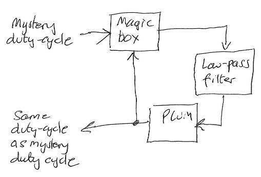
My proposed m/s-locked loop is much like a PLL, with the VCO replaced by a voltage-controlled pulse-width modulator, set to the desired output frequency.
To complete the loop, there is a low pass filter an a magic box that compares the mystery m/s of the input signal with the m/s of the PWM generator and, regardless of the frequency of either, produces a voltage related to the difference between the two ratios.
The difficult bit
So the magic box is the tricky bit here, as the other two parts are well known and can be done in various ways.
 Concept 1 for the m/s comparator is a pair of simple low-pass filters feeding an op-amp.
Each filter makes a voltage proportional to the m/s of its waveform, and the op-amp makes a voltage proportional to the difference.
This scheme also removes the need for a later later low-pass filter.
BTW, replacing the op-amp with a comparator would allow a mostly-digital loop, with its output controlling the direction of an up-down counter that sets the mark length within an all-digital PWM.
However, it does require the two incoming signals to have exactly the same amplitude – accurate to whatever the system accuracy demands – I was shooting for errors of 0.1%.
Could the need for accurate voltages be removed?
 Yes, I thought after several house with pencil in hand, and this is what I came up with.
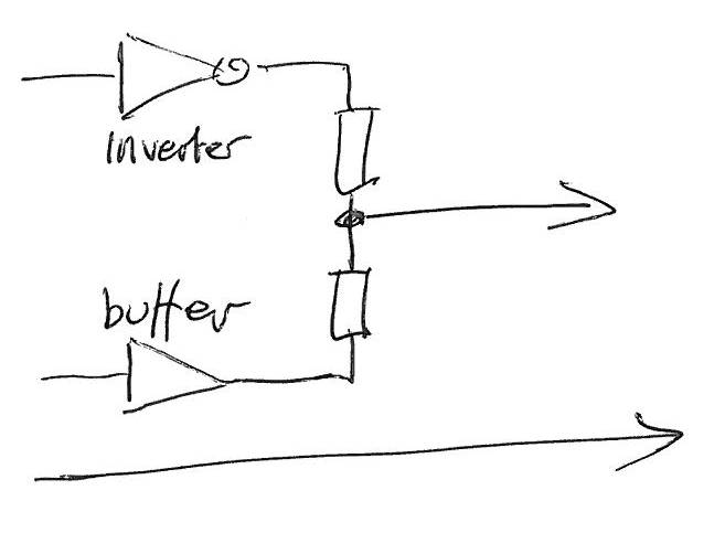
Using an inverter and a buffer means that the one resistor gets the m/s ratio of one input, and the other gets the s/m ratio of the other – the digital equivalent of using the inverting and non-inverting inputs of the op-amp.
If the resistors are matched, and by chance I picked out two that both measured 1,000.6Ω, then the average voltage at the resistor junction will be Vcc/2 of the logic supply when the two m/s ratios are identical – this is my claim, and so it has proved so far. A simple capacitor to ground from the junction does all the necessary low-pass filtering, and there is not need for precision in Vcc, so long as the output is compared with Vcc/2.
A confession is, that I cannot write a general equation for the m/s comparator so cannot say what the curve of m/s difference to output voltage is, and did not have time to measure it.
Quickly knocking up something with three HC inverters (HC04) in parallel for each resistor driver (feeding inverted PWM into one side to get the subtraction), and an apalling layout (see photo to be added) I got matches within 0.3% using a 30kHz PWM frequency and inputs between 10kHz and 300kHz with mystery m/s from 1/4 to 4/1.
This is pretty good, I feel, taking into account the rise and fall times of the input signals were not infinitesimal.
Up to 1MHz, it worked almost as well, and at 3MHz it was miles out – although still functioning. Time ran out for testing higher m/s ratios but a quick look at m/s=10 seemed fine. For 0.1% accuracy, duty cycles of 999 and 0.001 would both have to be good.
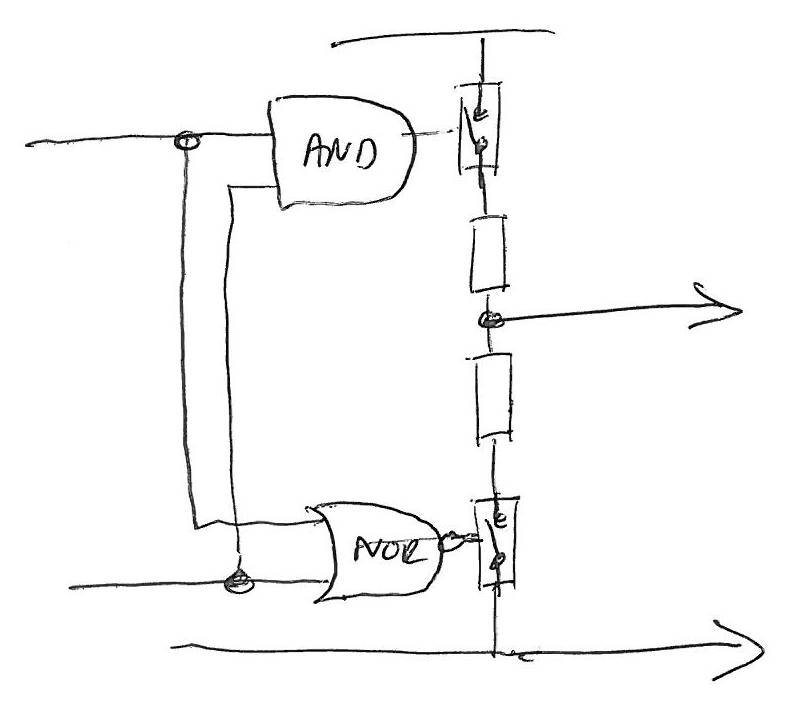 Slightly better results at high frequency were had from this arrangement, which does the same thing:
- output hi only for both inputs hi and
- output low for both low
- except that when they differ, the inverter version delivers Vcc/2 by potentiometer action, while this circuit delivers a high-impedance state.
Parts were HC02, HC08 and HC4066.
However, if both input frequencies are exactly the same, this version becomes a phase detector, and so cannot be reliably calibrated by putting the same signal into both inputs.
Why might this be useful?
This might seem entirely academic, but may be not.
The circuit that inspired me to ponder PWM measurement is a 300kHz switching power supply, and the PWM ranges of DMMs only go up to tens of kHz.
Frequency counters can be used, how many have a duty-cycle or m/s setting? – and measuring periods at 300kHz to 0.1% would need a nice counter with least a 300MHz clock and counter.
Which is why my thoughts turned to doing it with an Arduino with an LCD attached.
The PWM creation capability of Arduino is nominally only across 255:1 to 1:255, but can easily be set anywhere between 999:1 and 1:999 using one of the 16bit counters and a bit of extra code.
If the inverters in the m/s comparator are powered from the Arduino power supply (well decoupled please), and the internal 10bit (1,024) ADC is set to use its own 5V as a reference, and to measure the resistor summing junction (which will need the capacitor to ground), then the ADC will record 512/513 when the input and internally-generated mark/space ratios are the same, at which point the programme can display the m/s on the screen.
If they are different, an algorithm can alter the internally-generated m/s until the ADC does see 512.
At balance, everything is ratiometric, so the absolute value of Vcc and and the Arduino clock are irrelevant – they only have to stay stable during the measurement
If a check on validity is needed, the internally-generated signal can be fed into both m/s comparator inputs (inverted into one) which should deliver a reading of 512, and if it doesn’t, the number can be recorded and subtracted as an offset for future measurements. Auto-recalibration could be arranged.
[ad_2]
Source link