
[ad_1]

It is good? The short answer is excellent – particularly as it seems to be the work of a few people and not a giant team.
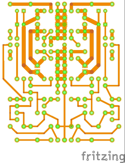
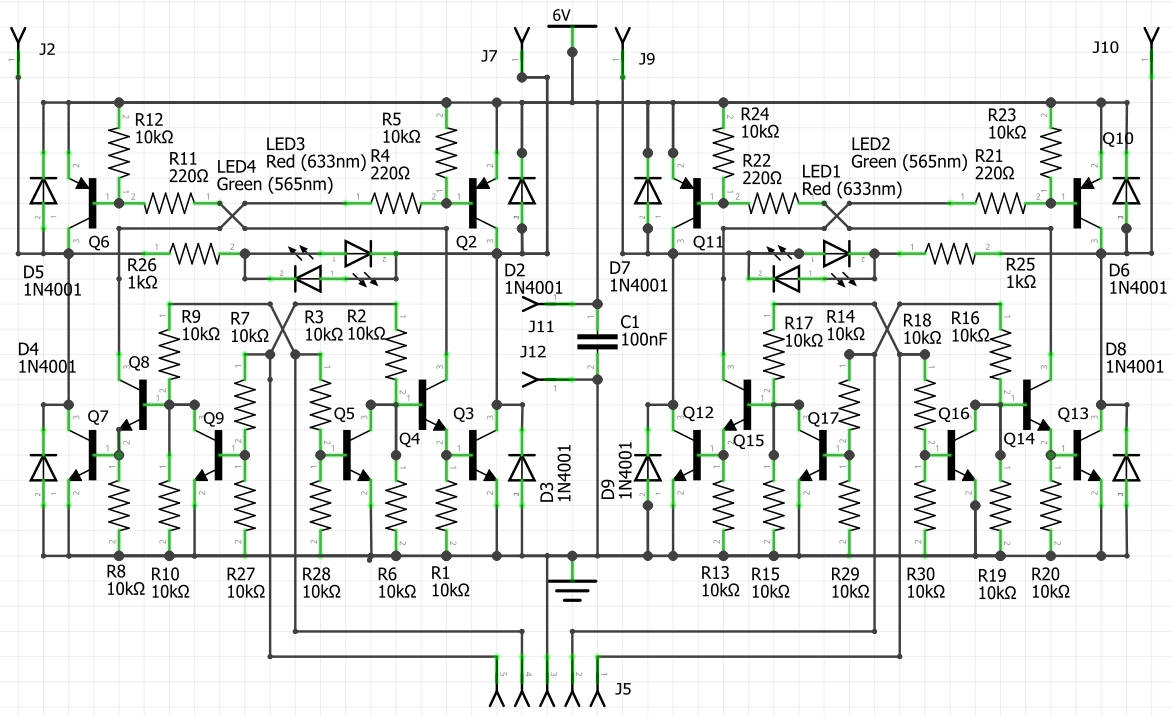
To try it out, I designing a pcb for interfacing an Arduino to two robot motors (scroll down here for original design), to which I have added a few more resistors to make sure all the transistors are fully off when there is no drive waveform – removing the need for a power switch in the 6V line, I claim – see circuit below.
A safety warning: there is no current limiting in this design. It is intended to be used with alkaline AA cells which self-limit around 4A so chances of a fire if the output is shorted or a motor is mechanically locked is low. If used with rechargeable cells, please add a fuse.
As I said, Fritzing proved to be excellent, although there are a few things small things I am struggling with.
One is that, in pcb view, I cannot find a way to make ratsnest connections links snap to nearby copper. Instead, the connections will only link component pins, which can leave them trailing half way across the board when really there is nearby copper that is already connected to the appropriate pin. In the free version of the Eagle pcb layout tool, this is not an issue.
Near the bottom left corner is an example where I cannot get he trace that runs diagonally beside Q4 and Q9 (image above) to connect neatly to the end of R9. If the track is doubled back, it appears to block the end holes of R10 and Q9.
 For etchable pdf, scroll to the bottom
Another, for which there is a work-around, is that if copper tracks are widened, the ends of them will protrude into the component hole at the end. Fatten them too much, and they block the hole completely – greatly hampering hand-drilling for diy pcbs.
The excellent work-around is to save the design, close it, then open it again, when all the holes blocked or partially blocked by this issue will be magically cleared out.
Related, it that – unless I am mistaken – Fritzing requires all tracks to be laid out 0.024″ wide and then re-sized. Whereas Eagle allows a current default to be set as they are laid out.
On this layout, resistors are allowed to overlap transitors in this case because the transistors are mounted some way above the board – to make room for their legs to be bent to the 0.1″ pitch of the mounting holes.
And I suspect someone less amateur than me could squeeze up the lower portion – be aware there are a couple of short resistors (R7 and R18) to get it this far, and a couple of vertical resistors in the middle (R8 and R20, labels under wire links in top diagram).
EMC
Some effort has been made to put fat tracks on the motor current paths and, to reduce radiated interference by reducing the area of high-current loops.
The small ceramic capacitor, say 1μF, in the centre of the board is there in an attempt to reduce fast voltage edges flying up the battery leads.
Less interference will be generated if the pairs of wires going to each motor are separately twisted, as well as the pair of wires going to the battery.
A further potential source of electrical noise are the brushes within each motor. A series RC combination – perhaps 10Ω and 0.1μF for each motor – connected directly across the motor terminals, might help.
 The driver
The driver circuit is a twin H-bridge, designed to be pretty fool-proof for teenagers, mainly for twin 6V motors running at up to 1A for the robot chassis that can be bough cheaply from various places – although it will easily handle current pulses above this, and rail voltages from 3V to 12V – but beware, the main power transistors will get hot if too much is asked of the circuit – there is no over-heating protection. And, as mentioned before, there is no over-current or short-circuit protection.
Control voltages (digital ‘high’ = ‘0’) on J5 can be anywhere from ~2V to 12V, so are compatible with 3V and 5V arduinos as well as Raspberry Pis and MicroBits. Current is low (~1mA at 5V). A digital ‘low’ (=’0′) needs <0.4V (say) on a control pin.
All resistor values can be optimised for particular combinations of control and battery voltages.
Moving a motor simply requires one of the input pins on connector J5 to be held low while its partner is held high or PWM-ed. PWM waveform up to a few kHz will be fine, and possibly up to a few tens of kHz.
- Pull pin 1 of J5 high or PWM it (with pin2 low) and the right hand red led (LED1) comes on and the motor across J9-J10 revolves in the red direction. (see table).
- Pull pin 2 of J5 high or PWM it (with pin1 low) and the right hand green led (LED2) comes on and the same motor revolves in the opposite direction.
- Pull pin 5 of J5 high or PWM it (with pin 4 low) and the left-hand red led (LED3) comes on and the motor across J7-J2 revolves in the red direction.
- Pull pin 4 of J5 high or PWM it (with pin 5 low) and the left-hand green led (LED4) comes on and the left motor revolves in the opposite direction.
This lot is summarised in the table below.
| J5 pin | right led | right motor (J9-J10) |
|
| 1 | 2 | ||
| 0 | 0 | none | no drive |
| 0 | 1 (or pwm) | green | one direction* (slower) |
| 1 (or pwm) | 0 | red | other direction (slower) |
| 1 | 1 | none | no drive** |
| J5 pin | left leds | left motor (J7-J2) |
|
| 5 | 4 | ||
| 0 | 0 | none | no drive |
| 0 | 1 (or pwm) | green | one direction* (slower) |
| 1 (or pwm) | 0 | red | other direction (slower) |
| 1 | 1 | none | no drive** |
Table notes
J5 pin 3 needs to be connected to Arduino 0V
*actual direction is established by swapping the motor terminal connections
** no drive, but some power consumed in the driver so battery will slowly flatten
Left and right circuits are completely separate, except for sharing a battery
To keep things simple, there is no braking mode – braking involves short-circuiting the motor by putting either both top transistors on, or both bottom transistors on (but definitely not all four of an H-bridge on, which would short-circuit the power rails as well as the motor).
Transistors Q5, Q9, Q16 Q17 are there to turn off the driver should both inputs of either H-brige be pulled high simultaneously. If they were omitted, pulling for example pin 1 and pin 2 of J5 high simultaneously would short-circuit the power rails and something would burn out.
The way the various base-emitter voltages stack helps (fingers crossed) this safety circuit to cut-in just before things go wrong.
Some resistors (R27 R28 R29 R30, and then R6 R10 R15 R19) are there to make absolutely sure off-means-off for all the transistors, and could be left out if the magic transistor fairy promises Q3 Q5 Q8 Q9 Q14 Q15 Q16 Q17 do not leak at all. With all these resistors in, leakage through the two H-bridges should be a few μA at most of all inputs are held low, or the controlling processor is disconnected – hence no need for a switch in the 6V supply – unless you need to protect against something conductive like a screwdriver accidentally being poked amongst the components.
Because it uses PNP transistor on the upper part of the H-bridges, this driver will give more powerful drive than many of the shields and HATs available commercially – as most are based on ICs that have NPN upper transistors, and therefore waste almost a volt.
Power is fed in positive to J11 and negative to J12. The centre pin of J5 is electrically-connected to J12 and must be connected to 0V on the controlling Arduino – so the board will connect Arduino 0V to the negative of the 6V motor battery.
Critical components
The control transistors Q3 Q5 Q8 Q9 Q14 Q15 Q16 Q17 can be any general purpose plastic NPN transistor – with the base connected to the middle pin to ease constriction. Don’t go by the D-shape on the pcb as transistors vary in pin layout, just make sure the collector is at the right end in each case.
2N3904 in TO-92 form is suitable and will match with the D-shape.
BC337, also TO-92, is also suitable electrically, but the emitter and collector are swapped physically so the shape is less compatible.
The main H-bridge transistors are special – they need to have high gain in saturation, and Diodes’ (once Zetex’) excellent ‘matrix emitter’ transistors fit the bill perfectly (read here to learn why).
These saturate to a small fraction of a volt, even at 1A with only 10mA of base drive, and therefore do not get anything like as hot as normal transistors, which would have a volt or two across them with so little base drive.
For the PNPs (Q2 Q6 Q10 Q11) you won’t go wrong with ZTX718 (20V 2.5A) or ZTX749 (25V 2A)
For the NPNs (Q2 Q7 Q12 Q13) you won’t go wrong with ZTX618 (20V 3.5A) or ZTX649 (25V 2A)
Make sure you get them the right way around – all eight emitters towards the central spine of the board.
Diodes also makes surface mount equivalents for all of the special transistors – be careful to put plenty of copper area on the collector of any surface mount version to drain heat away.
Hopefully, there will be a click to download the Fritzing file here, when we work out how to do that.
Here are the copper patterns for the pcb in etchable pdf form – straight and mirrored. Ot has not been tested yet.
Dual-motor-driver_etch_copper_bottom
Dual-motor-driver_etch_copper_bottom_mirror
With much thanks to the people who wrote and maintain Fritzing.
And the staff and pupils of a certain Oxfordshire school for inspiring this blog.
[ad_2]
Source link