
[ad_1]
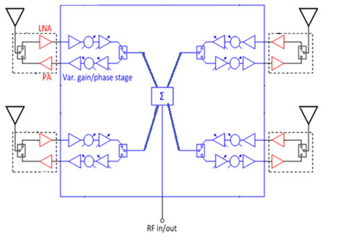
The chip, called ADAR1000, operates in half-duplex:
- In receive (Rx) mode the four Rx inputs are combined to a common RF_IO pin
- In Tx mode the RF_IO signal is split into the 4 Tx channels.
- In both modes, 31dB of gain control and 360° of phase control is provided
(>6bit resolution = <0.5dB and <2.8°)
The four pairs of Tx and Rx channels have independently programmable gain and phase settings, set via a digital serial interface. Settings can be loaded into built-in memory for fast access to selected Tx or Rx gain and phase states.
According to the firm: “The ADAR1000 is a plug-and-play chip that allows designers with little or no RF experience, without the need for extensive third-party design support, to extend the performance and operating lifetime of their radar systems.” Applications are foreseen in defence, surveillance, air traffic control, communications and weather monitoring, as well as flat-panel antenna arrays for aircraft.
To reduce the RF part of a phased array antenna to a single planar assembly, the chip has been designed to sit flat on the back of an patch antenna array, positioned between four patches on the other side, feeding and receiving from the patches via four combined LNA/PA +T/R switch (low-noise amplifier/power amplifier + transmit/receive switch) chips – such as the firm’s own ADTR1101.
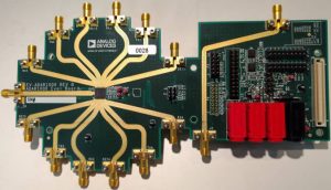
ADAR1000-EVALZ is an evaluation board for the chip.
Features
- 8-16GHz
- Half-duplex time-domain division for Tx and Rx
- Single-pin Tx/Rx control
- Versatile T/R modules control modes
- 360° phase control at <2.8°resolution
- >31dB gain control with 0.5dB resolution
- On-chip memory for pre-stored beam positions
- Auxiliary 8bit ADC for power detectors and temperature sensor
- 4-wire SPI interface
- 7 x 7mm LGA package
[ad_2]
Source link