
[ad_1]
And it all seemed so simple until I started reading around to understand it.
I supposed I should have guessed, but the risk is that you end up with two gain peaks in the transfer function if the Q in the various resonances is too high – pushing signals at those frequencies back into the power source.
Also, output impedance in the forward direction – at the right-hand end – can mess with a following power converter, it appears.
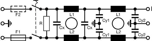
I am assuming Schurter has damped its design wonderfully (diagram above), with capacitor series resistance, inductor parallel capacitance, or some other scheme.
If you want to damp something similar, TI’s ‘Input filter design for switching power supplies‘, which was once a Nat Semi app note, is the best resource I have yet found.
[ad_2]
Source link