
[ad_1]

A 4×7 array of touch points delivered by eight connections using Binstead’s patented scanning technique.
It is said to work with both resistive and projected capacitance screens, and only requires connection along one edge of the display.
“In the arrangement, there are no fixed receiving or transmitting conductive elements – each element being considered as transmitting or receiving at different stages in the scanning cycle,” system inventor Ron Binstead told Electronics Weekly.
 In an example of the scheme (see diagrams top and bottom) 28 touch points are delivered by eight connections, instead of the usual 16.
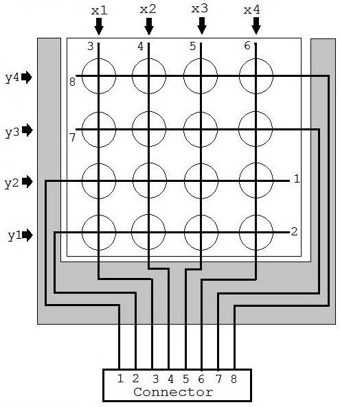
Standard scanning delivers 16 touch points from eight connections, and can require no-touch zones on three sides (grey)
The system uses diagonal connections (see bottom diagram) for the pure diagonal arrangement, or it can be distorted to provide a rectangular array of touch points (top).
Each element starts at the connector edge and runs diagonally through the touch-screen to a second edge, where it 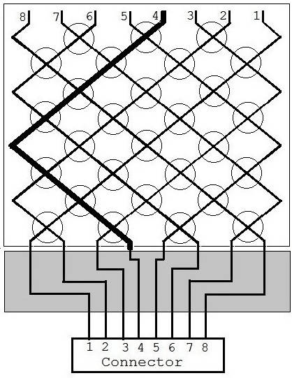 changes direction and runs through the touch-screen again until it reaches a third edge, opposite the connector (see emphasised conductor 4).
Even numbered elements run in one direction while odd numbered elements run in an opposing direction.
“This arrangement results in each element intersecting all the other elements, resulting in a significant increase in the number of intersections,” said Binstead. “It also eliminates any non-touch zones [shown grey] along the sides of the touch-screen.”
And, if the connections (grey part) to the diagonal arrangement are folded under the display, there are no no-touch zones.
When ‘n’ is the number of connections, the standard x/y array has a maximum of n2/4 intersections, while diagonal lattice offers (n2-n)/2 .
In a 9:16 format, the diagonal lattice array has almost double (1.93x) the number of touch-points than an x/y – 4450 (50×89) rather than 2304 (36×64) for 100 connections.
Or fewer connections are required for the same touch-point density.
“For example, Microchip’s MTCH6301 touch controller is a 44pin TQFP with 18 transmit pins and 13 receive pins,” said Binstead. “This could be replaced with a 36pin device with no loss of function.”
All conductive tracks are a similar length and follow similar routes in the diagonal scheme.
“If a 9:16 X/Y format is used, then the horizontal and vertical conductive elements can be nearly twice as long in one direction as they are in the other direction,” said Binstead. “This factor can lead to variation in sensitivity over the touch-screen.”
However, he points out, if the same scheme was executed with diagonal wiring, conductors are ~12% longer than the longest elements in an x/y array.
Lastly, with diagonal lines Binstead sees less interference from the underlying LCD line-scan signals.
As well as this intellectual property (IP), the company has patented an ITO-replacement technology for conductors using fine insulated wires, that results in a touchscreen that is “very thin and flexible, being about 100μm thick”.
By combining diagonal sensing and the ITO alternative, multi-finger sensing is possible through glass between 0.5mm and 20mm thick, said Binstead.
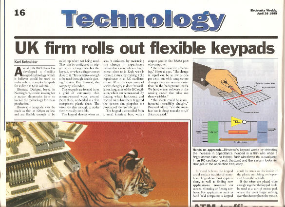 In 1995, Electronics Weekly featured earlier Binstead IP, which was subsequently licensed to Zytronic Displays.
[ad_2]
Source link