
[ad_1]
This sensor requires two PCBs, one on the rotating shaft and a static one through which the shaft passes.
The two PCBs only need to be made to conventional tolerances – with 0.2mm track and gap.
Even though radial and axial mechanical positioning requirements are generous at +/-0.5mm, linearity is +/-0.22°.
“Optical sensors would probably need to be within 20μm,” said founder and director David Ely.
 Custom parts are two transponder coils mounted on the rotating part, and one of the firm’s sensing ICs on the static PCB.
Part CAM204 will operate two such sensors, while high-speed CAM504 works with a single shaft at up to 20,000rpm.
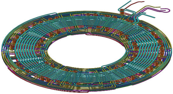
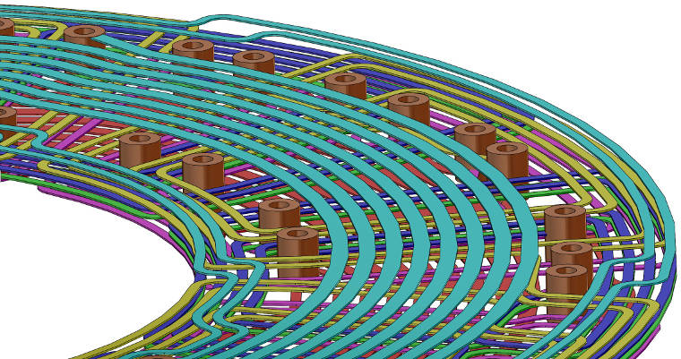 The static sense PCB has six layers. Rendered with SolidWorks, the top and bottom two (pale blue and just visible red) have circular drive coils plus meandering course (anti-ambiguity) sense coils (inner and outer edges). The other four layers provide fine sense coils.
Tens of thousands of this particular sensor are deployed, mostly inside motorised surveillance cameras where they measure which way the camera is pointing.
Detailed operation is described here.
Last year CambridgeIC won a Queen’s Award for International Trade , and this week it is celebrating its 10th brithday.
[ad_2]
Source link