
[ad_1]
Compared to other frequently used batteries, lithium-ion batteries are known for having a high energy and power density, a long service life and for being composed of low-pollution materials.
Lithium is the lightest metal in the chemical periodic table (atomic mass of 6.941 g/mol; density of 0.53 g/cm3) and has the largest electrochemical potential of all metals (3.0 V vs. standard hydrogen electrode).
Lithium batteries
The resulting high electrical capacity and the high cell voltages which can be achieved in combination with various different cathode materials make it the ideal electrode material for chemical energy storage devices. As such, lithium batteries are being increasingly used in all areas of everyday life. They are primarily used as a self-contained power supply independent from the mains and as buffer batteries for electronic devices.
The boom in small mobile electronic devices (smartphones, notebooks, cameras and tools, etc.) in particular has led to their massive widespread deployment. However, lithium batteries are also being used more and more in the small vehicle segment.
The growth in the use of lithium batteries in the automotive industry (e.g. hybrid drivetrains and high-voltage electric drivetrains, etc.) is currently nothing short of phenomenal.
For example, the German government has announced its goal to increase the number of electric vehicles to 6 million by 2025, which must go hand in hand with with a further development of the lithium battery system. The suitability of an electromechanical energy storage device for use inside electric vehicles in particular depends on a variety of technical, economic and ecological aspects.
On that point, the United States Advanced Battery Consortium (USABC) has identified safety and service life, in addition to energy density, as key indicators for setting battery development goals and measuring any progress made.
Additionally, though, there are also specifications for battery systems laid down in the automotive industry: cost-effective solutions with high power and energy density are required, which noticeably restricts the usable volumetric and gravimetric overhead, which is available for the battery design and the thermal management.
Automotive and safety
The use of lithium batteries in the automotive industry is marred with thermal safety concerns due to their high capacity in particular in high series connection.
The reason is that lithium batteries can only be used within a clearly prescribed operating range defined by temperature and voltage.
Outside of that range, the use of lithium batteries can quickly lead to a reduction in performance and also safety risks (you only have to think of the Dreamliner battery fires from 2013 or when HP once again had to recall over 100,000 notebooks due to severe fire risks at the beginning of 2017).
In consideration of the instructions from most battery manufacturers, the safe temperature ranges for current automotive lithium batteries (graphene/LiMn2O4 or abbreviated to C/LMO, C/LiCoxNiyMnzO2 or C/NCM, C/LiFePO4 or C/LFP, C/LiNi0.8Co015Al0.05O2 or C/NCA) are as follows: discharge at -20°C to +55°C and charge at 0°C to +45°C.
For lithium-ion batteries with Ki4Ti5O12 or LTO negative electrode, the low temperature value is -30°C. The operating voltage of lithium-ion batteries is normally between 1.5 V and 4.2 V, (C/LCO, C/NCA, C/NCM and C/LMO between 2.5 V and 4.2 V, for LTO/LMO at 1.5 V to 2.7 V and for C/LFP between 2.0 V and 3.7 V).
As the temperature increases, lithium batteries react by increasing the pressure in the cell, emitting flammable gases and setting the cell on fire, culminating in a vicious, self-reinforcing cycle whereby the battery explosively burns away (thermal runaway). As such, the use of high temperatures is problematic and leads to damage and failure.
- +70°C: Self-heating of the graphite anode and the electrolytes. Low-boiling components in the electrolytes begin to vaporise at 80°C and lead to the build-up of pressure which can cause the cell to burst.
- +130°C: Separator made of PE, PP or PE/PP wears away the pores (shut-down). Separator melts, additional heating due to short-circuit, autocatalytic increase in temperature
- +250°C: Cathode materials react exothermically with the electrolytes (decomposition). Increase in pressure in the cell due to vaporisation and decomposition gases. Swelling of the cell housing and potential opening (escaping decomposition gases are flammable). Some cathode materials already spontaneously decompose at temperatures below +200°C and emit heat and oxygen in an exothermic reaction, which can lead to thermal runaway.
- +600°C: Cathode materials decompose and their crystalline structure is altered. Release of oxygen. Cell fire within a short period of time. Thermal runaway.
- +660°C: Melting of the aluminium current collector (cathode). Release of graphite with potential hazard on account of dust explosion. Further increase in temperatures at which aluminium sheet of the positive electrode starts to burn (metal burn).
With regard to thermal management, traction batteries are subject to a broad range of operating conditions. As such, varying external temperatures represent a huge challenge for thermal management and cannot be compared to the conditions under which lithium batteries are used in consumer electronics.
For example, the usable capacity is reduced on cold days because the cut-off voltage is reached earlier whereby the vehicle’s range is reduced. Another challenge is the guaranteed service life, which must be defined as eight to ten years for the automotive industry.
This is closely connected to the battery system’s thermal management. The speed of cell ageing is dependent on the temperature and manifests itself in the form of a decline in capacity and increase in internal resistance.
End of life condition
As such, the end-of-life condition is defined specifically depending on the application and is arrived at when 80% of the original capacity is reached and/or the internal resistance is doubled. The ageing rate at temperatures above the optimal range can be approximated using the Arrhenius equation: for every 10K temperature increase, the cell’s service life is halved.
It is therefore important to emphasise that not only the average cell temperature but also the temperature gradient within a cell and between the cells is critical.
Non-uniform heat distribution has been proven to contribute to premature ageing and capacity reduction by creating local “hotspots”.
Temperature differences between the cells cause the cells to age at different rates: in a chain of cells connected in a series, the weakest cell reduces the service life of the system. Therefore, both the average temperature and the temperature differences in the battery thermal management system (BTMS) need to be taken into consideration. In summary, the ideal situation is to have a uniform and consistent temperature distribution in the battery system.
The study “Spatial and Temporal Temperature Homogenization in an Automotive Lithium-Ion Pouch Cell Battery Module” [Gepp, Lorentz, März, Geffray & Guyon, 2017] recently published by the Fraunhofer Institute for Integrated Systems and Device Technology IISB (Erlangen) specifically looked at that problem.
“There is a clearly identifiable trend: the energy density of lithium-ion cells will continually increase whereby the range of battery electric vehicles will be improved in the near future. However, when the amount of energy increases, so too do the risks.”
“By implication that means that safety aspects will become increasingly important and will have to be taken into consideration a lot more in the design process. And that is where, for us, thermal materials became particularly interesting in order to provide an economically feasible alternative to expensive cooling management solutions”, explains Markus Gepp, who spearheaded the study and whose findings will be explored in more detail here.
The interesting aspect of his approach is the optimisation of thermal management, by integrating new materials, and thus also the considerable reduction in size and volume. The module structure of the presented BTM design is described in Fig. 1 below, which reflects a sectional view from above:
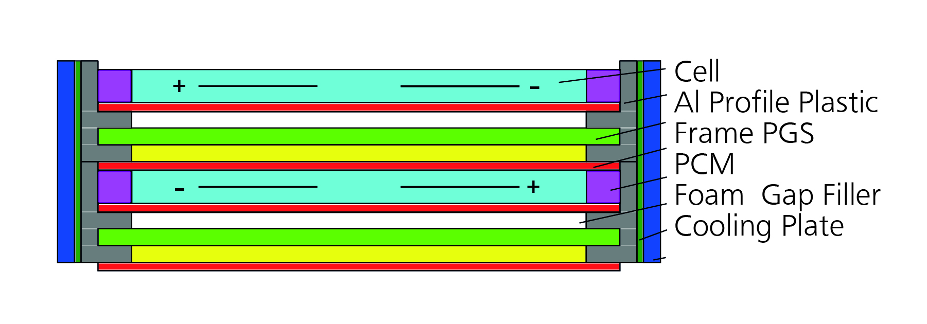
Figure 1 – Concept of the mdule in cross section view
Pyrolytic graphite sheets
What’s more, a pyrolytic graphite sheet (PGS) was used as the heat distributor, which is a new ultra-light graphite sheet developed by Panasonic, the thermal conductivity of which is five times higher than that of copper.
The pyrolytic graphite sheets are stuck directly on to and fully flush with the cell surfaces and bound with PCM and metal profiles using flexible and thermally conductive adhesives.
The elastomer-based phase change material is set up in such a way that, due to its additional latent heat absorption, it acts as a buffer in the upper operating temperature range of the cells. As such, it is thermally connected in parallel to the heat path between cells and cooling plates, whereby the path is not interrupted.
The aluminium profiles are designed as shaped inlays for the cast plastic frame and provide mechanical stability and a thermal interface with the cooling plates.
Commercial fluid cooling plates are bound with compressible gap fillers in order to compensate for geometric and production-related tolerances whereby air gaps can be eliminated. All cells are connected in series by means of ultrasonic welding. The advantage of this design is that the manufacturing process is economically cost-effective even for small quantities. Fig. 2 shows the assembled prototype.
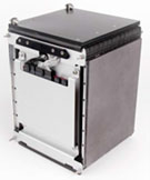
Figure 2 – Battery module prototype
Thermal design
The thermal design of the battery module was developed in close cooperation with various different industry partners and is based on the integration and interaction of thermal material solutions. The frames with the integrated components are shown in Fig. 3.
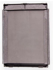
Figure 3 – Frame including PGS foil and PCM inlays
When it came to the implementation, the decision was quickly made to incorporate Panasonic’s PGS, which Gepp explains as follows:
“We initially began to work with a pouch cell module with fixed graphite cooling plates. However, PGS then caught our attention on account of its low material density of 70µm, flexibility/bending cycle stability and high conductivity of 1,000 W/m.K.
In addition, the sheet could be directly attached to the pouch cell without any further procedures, thus ensuring low thermal contact resistance. Also, the problem of the volume increase of the cells, which occurs both within a charging cycle and over the service life, could be compensated for by the flexible sheets through corresponding relief folds in combination with foams.”
The results of this design speak for themselves and can be referenced using the following three criteria:
- The degree of spatial homogenisation, which can be defined based on the maximum measured temperature difference between the cells.
- The degree of temporal homogenisation, which is determined through the maximum thermal resistance and therefore is in reference to the maximum temperature increase/dissipating power loss relationship.
- The overhead, which is measured and stated in terms of weight and volume and therefore makes the mechanical design quantifiable and comparable independently of the cells.
Spatial temperature homogenisation
A 50 A (2C) charge current with 10 A cut-off at 48 V and 130 A (5C) discharge current with cut-off at 35 V is created as a test cycle (Fig. 4). The initial temperature, the ambient temperature and the coolant temperature are set at 20°C.
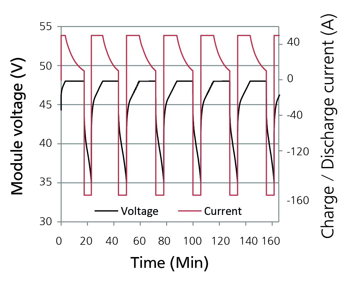
Figure 4 -Electrical load cycle
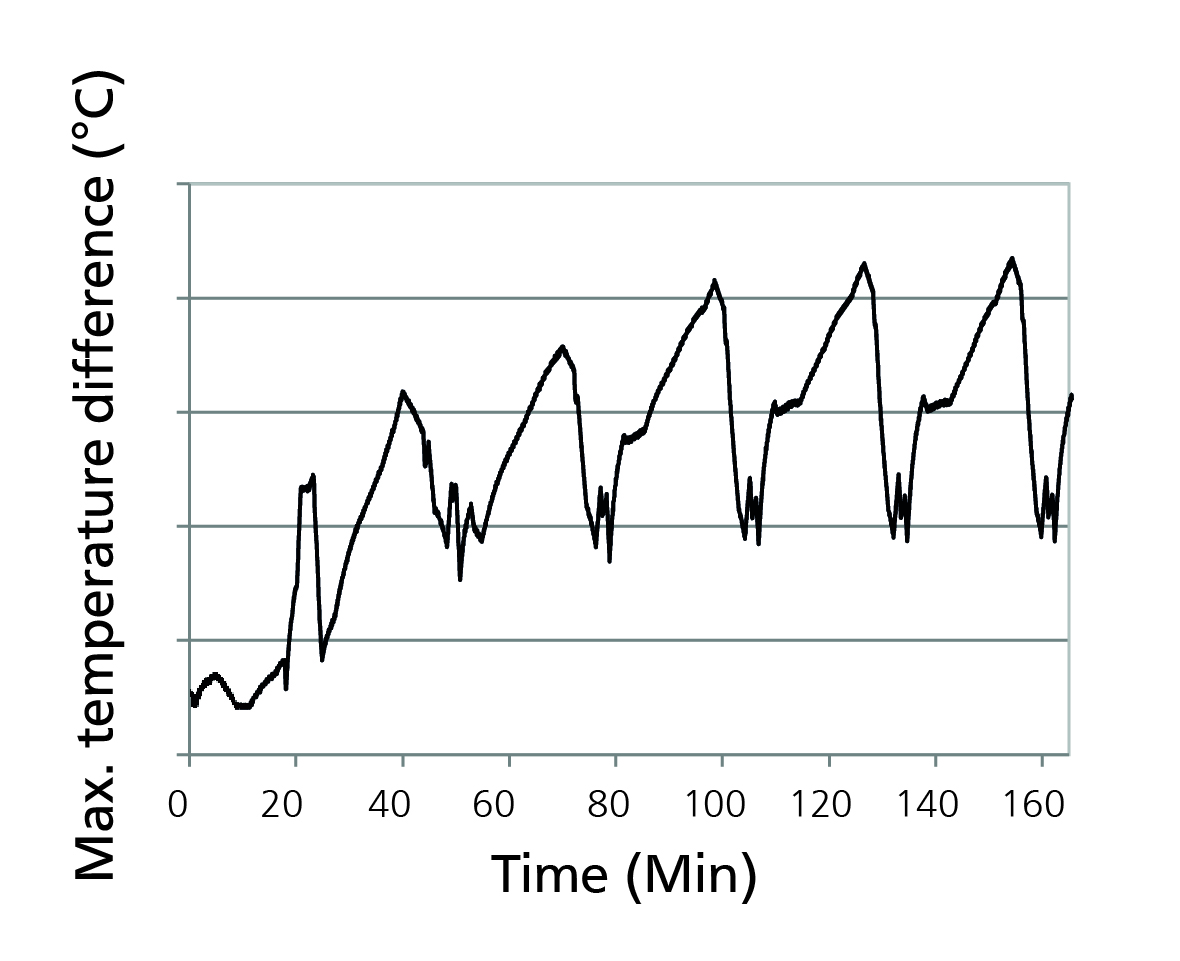
Figure 5 – Maximum temperature difference
Figure 5, above, shows the maximum temperature difference between the hottest and coldest cell with a peak of 4.3ºC. This comparatively low value is achieved because the cells have a good thermal connection thanks to the graphite sheets but at the same time are thermally insulated from each other by the frames.
As a consequence, the maximum gradient between the warm middle and cold outer cells could thus be reduced.
Maximum thermal resistance
In order to calculate the maximum thermal resistance, the maximum temperature increase and the dissipated power loss must be known when the system is in a stationary state.
To that end, the fluid-cooled module is continually cycled inside an insulated temperature chamber in order to achieve an almost constant heat dissipation until the stationary state is achieved.
The temperatures of the cells and the cooling plates are measured. The extracted thermal output can be determined from the flow rate and the temperature increase of the coolant.
A reduced flow rate leads to a bigger temperature increase of the coolant and thus improves the measurement accuracy. The result recorded is a maximum thermal resistance of 0.12 K / W between cells and coolant, which means a temperature increase of 0.12°C per watt of power loss arising in the cells.
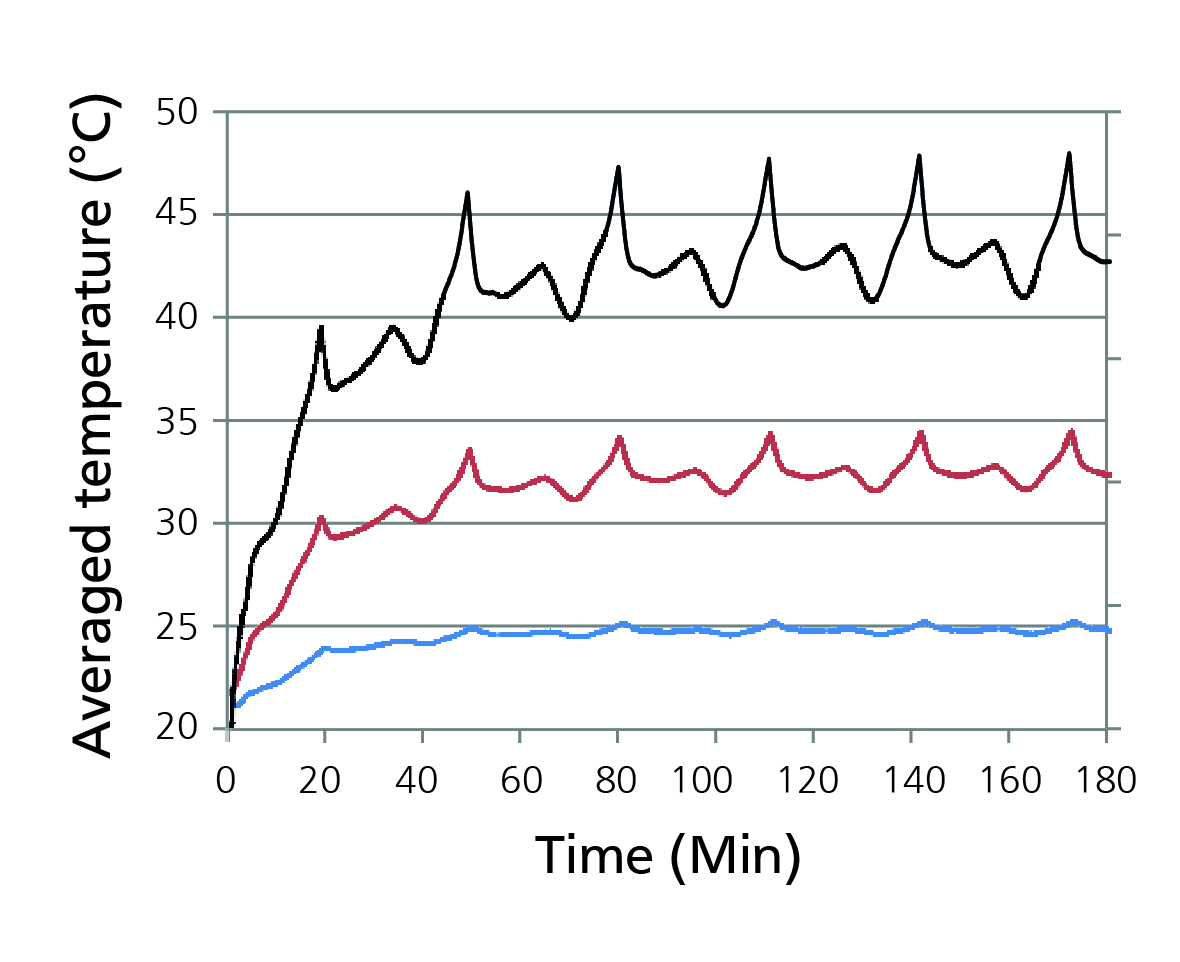
Figure 6 -Average mean temperatures of the cells and cooling plates
Overhead evaluation and specifications
The gravimetric and volumetric overheads refer to the weight and volume of the cell as listed in Table 1. The Vauxhall Ampera battery module with comparable pouch cells from LG Chem is used as a reference.
Thanks to the frame design with Panasonic’s thin and light graphite sheets as heat distributors, despite the integration of additional phase change material the overhead could be reduced in terms of weight by 25% and in terms of volume by 10%.
Summary
Thanks to the measuring of a prototype, this study was able to demonstrate how, by combining and adapting various different materials, thermal management could be optimised with an impact on the service life and safety of the battery module.
The battery module presented was constructed, assembled and tested in order to demonstrate measures for spatial and temporal temperature homogenisation. As such, conventional aluminium cooling plates were replaced with thin and light graphite sheets (PGS) from Panasonic.
New elastomer-based gap filler pads and cast compressible elastomer-based PCM inlays were developed and integrated into the system and connected with flexible and thermally conductive adhesive.
The measurements recorded showed a maximum temperature difference between the cells of 4.3°C in a continuous cycle with maximum permissible discharge current, a maximum thermal resistance of 0.12 K / W at module level and a reduced gravimetric and volumetric overhead.
Simone Saile, Product Marketing Manager in Custom Components Team, Panasonic Industry Europe
[ad_2]
Source link